Npe-g1 or npe-g2 optical cable-management bracket, Two-post or four-post rack installation – Cisco 7200 VXR User Manual
Page 16
16
NPE-G1 or NPE-G2 Optical Cable-Management Bracket
Step 1
Loosen the left and right captive installation screws.
Step 2
Hold the cable-management bracket so that it is positioned as shown in Figure 10.
Step 3
Place the left end of the cable-management bracket over the screw.
Step 4
Rotate the cable-management bracket down, until it slides behind the right captive installation screw.
Step 5
Tighten both captive installation screws.
Go to the “Two-Post or Four-Post Rack Installation” section on page 16.
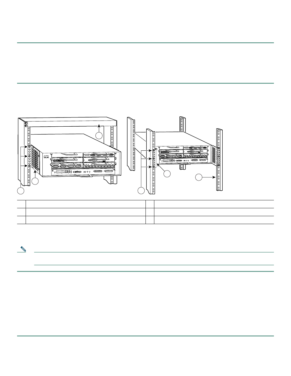
Figure 11
Installing the 7200 VXR in a Two-Post and Four-Post Rack
Two-Post or Four-Post Rack Installation
Note
Inner clearance (the width between the inner sides of the two posts or rails) must be at least 17.00 inches (43.18 cm).
The height of the chassis is 5.25 inches (13.34 cm).
Step 1
Make sure that all chassis screws holding the network processing engine or network services engine, I/O controller, and
power supply are tightened and that any port adapter levers are in a locked position.
Step 2
Make sure the rack brakes are locked or the rack is stabilized.
Step 3
With the router front closest to you, lift it carefully into the rack. To prevent injury, avoid any sudden twists or moves.
Step 4
Slide the chassis into the rack, until the brackets meet the mounting strips or posts on both sides of the rack.
Step 5
Keeping the brackets flush against the posts or mounting strips, align the holes in the brackets with the holes on the
rack or mounting strip.
Step 6
For each bracket, insert and tighten three 10-32 x 3/8-inch slotted binderhead screws, using the top, bottom, and one
other location on the bracket.
1
Two-post rack
4
Four-post rack
2
Rack-mount bracket
5
Rack-mount bracket
3
10-32 x 3/8-inch slotted binderhead screws
6
10-32 x 3/8-inch slotted binderhead screws
57108
2
ETHERNET-10BFL
E
N
R
X
0
1
2
3
4
TX
R
X
TX
R
X
TX
R
X
TX
R
X
TX
ETHERNET 10BT
EN
A
B
LE
D
0
2
1
3
LI
N
K
0
1
2
3
0
4
1
3
5
6
FAST SERIAL
EN
TD
TC
R
D
R
C
LB C
D
TD
TC
R
D
RC
LB
C
D
TD
TC
R
D
R
C
LB C
D
TD
TC
R
D
R
C
LB
C
D
ENAB
LED
M
II
L
IN
K
R
J4
5
FAST ETHERNET
0
TOKEN RING
0
1
2
3
ENABLED
IN-RING
4/16 Mbps
Cisco 7200
Series
FAST ETHERNET INPUT/OUTPUT CONTROLLER
ENABLED
PCMCIA
EJECT
SLOT 0
FE
ENABLEFE LINK
CPU RESET 1O POWER
OK
SLOT 1
FE MII
5
2
ETHERNET-10BFL
E
N
R
X
0
1
2
3
4
TX
R
X
TX
R
X
TX
R
X
TX
R
X
TX
ETHERNET 10BT
EN
ABL
ED
0
2
1
3
LINK
0
1
2
3
0
4
1
3
5
6
FAST SERIAL
EN
TD
TC
R
D
RC
LB C
D
TD
TC
RD
RC
LB
CD
TD
TC
RD
RC
LB CD
TD
TC
RD
R
C
LB CD
EN
A
B
LE
D
M
II
L
IN
K
R
J4
5
FAST ETHERNET
0
TOKEN RING
0
1
2
3
EN
ABLED
IN
-RING
4/16 M
bps
Cisco 7200
Series
FAST ETHERNET INPUT/OUTPUT CONTROLLER
ENABLED
PCMCIA
EJECT
SLOT 0
FE
ENABLEFE LINK
CPU RESET 1O POWER
OK
SLOT 1
FE MII
1
2
4
3
6