Replace the i/o controller, I/o controller, Captive installation screws – Cisco 7200 VXR User Manual
Page 37
37
Note
If you have difficulty installing a processing engine or I/O controller in the lowest slot of a Cisco 7200 VXR
router that is rack-mounted, remove the port adapters, processing engine and I/O controller from the chassis
and reinstall them. Install the processing engine and I/O controller in the lowest slots first, then populate the
slots above them, in a bottom-to-top order.
Step 5
Grasp the handle and pull the NPE or NSE from the chassis.
Step 6
Insert the NPE or NSE and tighten the captive installation screws.
Step 7
If you are replacing an NPE-G1, install the cable-management brackets and cables. See Figure 6 and Figure 9.
Step 8
Connect the router to the power source and power up the router.
See the
http://www.cisco.com/en/US/docs/routers/7200/install_and_upgrade/network_process_engine_install_config/npense.html.
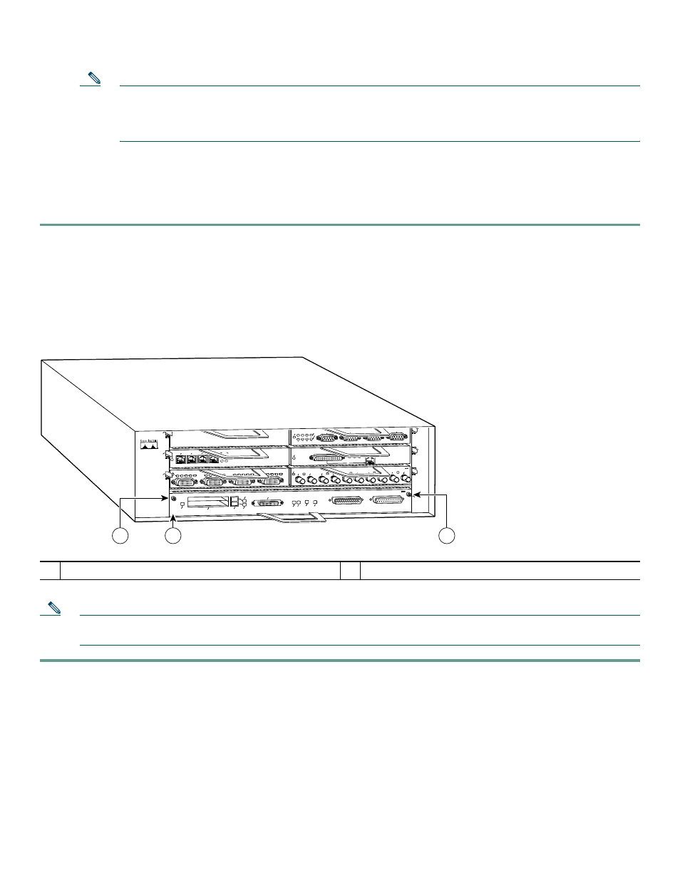
Replace the I/O Controller
Figure 19
Replacing the I/O Controller
Note
Before powering down the router, use the copy running-config tftp command to save the router’s running configuration
to a TFTP file server.
Step 1
Power off the router.
Step 2
Disconnect the router from the power source.
Step 3
Remove any I/O controller cables.
Step 4
On the I/O controller (1), unscrew the captive installation screws (2), grasp the handle, and pull the I/O controller from
the chassis.
1
I/O controller
2
Captive installation screws
2
ETHERNET-10BFL
EN
RX
0
1
2
3
4
TX
RX
TX
RX
TX
RX
TX
RX
TX
ETHERNET 10BT
EN
A
B
LE
D
0
2
1
3
LI
N
K
0
1
2
3
0
4
1
3
5
6
FAST SERIAL
EN
TD
TC
RD
RC
LB CD
TD
TC
RD
RC
LB
CD
TD
TC
RD
RC
LB CD
TD
TC
RD
RC
LB CD
EN
A
B
LE
D
MII
LINK
RJ45
FAST ETHERNET
0
TOKEN RING
0
1
2
3
ENABLED
IN-RING
4/16 M
bps
Cisco 7200
Series
FAST ETHERNET INPUT/OUTPUT CONTROLLER
ENABLED
PCMCIA
EJECT
SLOT 0
FE
ENABLEFE LINK
CPU RESET 1O POWER
OK
SLOT 1
FE MII
57015
1
2
2