Brackets front-mounted-chassis recessed in rack, Brackets front-mounted—chassis recessed in rack – Cisco 7200 VXR User Manual
Page 11
11
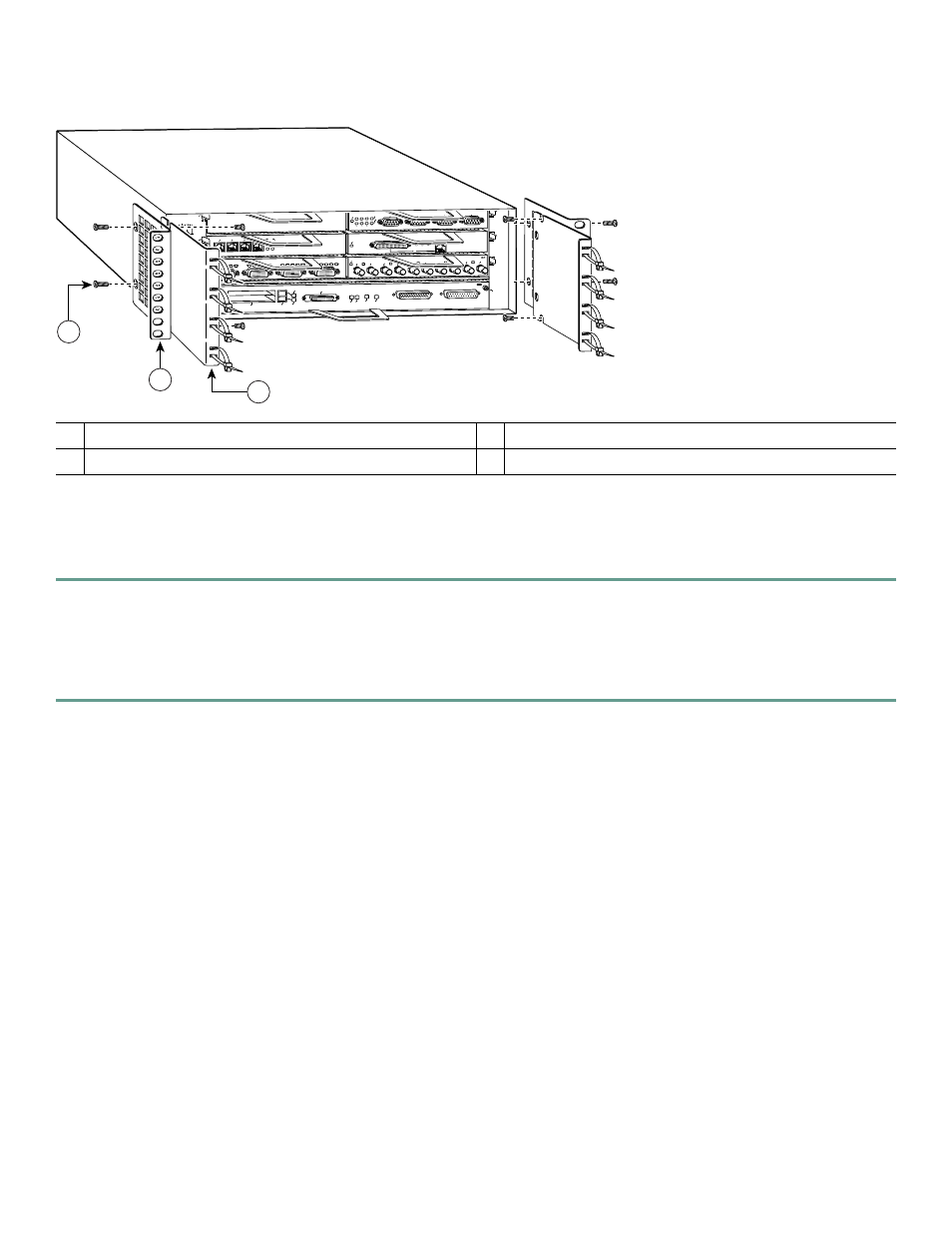
Figure 5
Attaching the Rack-Mount Brackets to the Front of the Chassis—Chassis Recessed
Brackets Front-Mounted—Chassis Recessed in Rack
Locate the rack-mount and cable-management brackets and screws and a Number 2 Phillips screwdriver.
Step 1
Align the cable-management bracket (1) to the side of the router. Align the rack-mount bracket over it—as shown
above—and insert and tighten the screws (3).
Go to the “Two-Post or Four-Post Rack Installation” section on page 16.
Step 2
If you are not using the cable-management brackets, align the rack-mount brackets (2)—as shown above—to the router
and insert and tighten the screws.
If you have an NPE-G1 or NPE-G2 installed, go to the “NPE-G1 and NPE-G2 Rear Cable-Management Brackets on a
Front-Mounted Router” section on page 12.
If you do not have an NPE-G1 or NPE-G2 installed, go to the “Two-Post or Four-Post Rack Installation” section on page 16.
1
Cable-management bracket
3
M4 x 8-mm Phillips flathead screws
2
Rack-mount bracket
2
ETHERNET-10BFL
E
N
R
X
0
1
2
3
4
TX
R
X
TX
R
X
TX
R
X
TX
R
X
TX
ETHERNET 10BT
EN
A
B
LE
D
0
2
1
3
LI
N
K
0
1
2
3
0
4
1
3
5
6
FAST SERIAL
EN
TD
TC
R
D
R
C
LB C
D
TD
TC
R
D
R
C
LB C
D
TD
TC
R
D
R
C
LB
C
D
TD
TC
R
D
R
C
LB C
D
EN
A
B
LE
D
M
II
L
IN
K
R
J45
FAST ETHERNET
0
TOKEN RING
0
1
2
3
ENABLED
IN-RING
4/16 Mbps
Cisco 7200
Series
FAST ETHERNET INPUT/OUTPUT CONTROLLER
ENABLED
PCMCIA
EJECT
SLOT 0
FE
ENABLEFE LINK
CPU RESET 1O POWER
OK
SLOT 1
FE MII
EN
53499
1
2
3