Transformer wiring, Zone addressing – Braeburn 140424 User Manual
Page 9
Transformer Wiring
3.3
24V
24C
C
C
HOT
Dedicated
Zoning Transformer
Zone
Panel
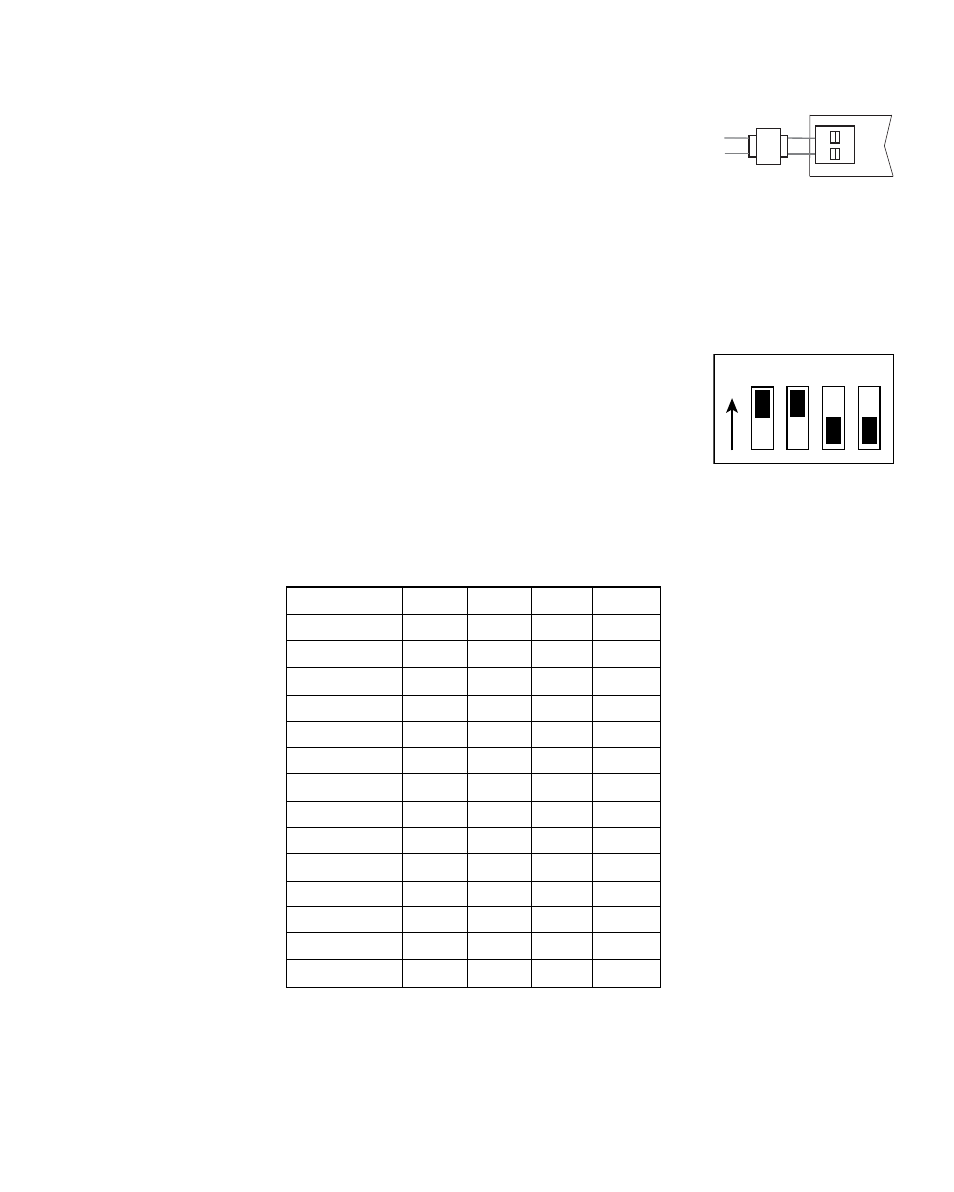
Zone Addressing
4
Use the following instructions to identify the zones on the zone panel expander.
No other configuration is necessary on the zone panel expander. Carefully slide
the dip switches to match the new zone numbers.
Use the open area provided on the expander panel to mark the new zone
numbers. When setting the switches to identify the expander panel, use a pen
or small screwdriver. Do not use a pencil, which may contain conductive material
in the writing point.
Switch Position
Zone ID 1
2
3
4
5 and 6
OFF
OFF
OFF
OFF
7 and 8
ON
OFF
OFF
OFF
9 and 10
OFF
ON
OFF
OFF
11 and 12
OFF
OFF
ON
OFF
13 and 14
OFF
OFF
OFF
ON
15 and 16
ON
ON
OFF
OFF
17 and 18
ON
OFF
ON
OFF
19 and 20
ON
OFF
OFF
ON
21 and 22
OFF
ON
ON
OFF
23 and 24
OFF
ON
OFF
ON
25 and 26
OFF
OFF
ON
ON
27 and 28
ON
ON
OFF
OFF
29 and 30
ON
ON
OFF
ON
31 and 32
ON
OFF
ON
ON
9
O
N
1 2 3 4
Install the transformer using the instructions provided by the manufacturer. Size
the transformer to the damper requirements. The zone panel has a built-in, self-
resetting fuse. The maximum damper power per zone is 75 VA at 24 VAC. Connect
the transformer to the zone panel as shown.
NOTE: Additional dampers or
dampers with a higher current draw will require the use of a separate slave relay.
ALWAYS PROVIDE DISCONNECT AND OVERLOAD PROTECTION AS REQUIRED
Example Switch Position
for Zones 15 and 16