Damper wiring, Thermostat wiring, Conventional thermostats – Braeburn 140424 User Manual
Page 7
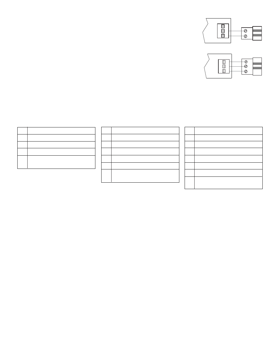
Damper Wiring
3.1
Install the system dampers using the instructions provided by the manufacturer.
Connect the dampers to the zone panel expander as shown for either a 2-wire
or 3-wire damper. The sum of all dampers powered by the zone panel should
not exceed 75 VA at 24 VAC. Use a slave relay if additional damper power
is required.
ALWAYS PROVIDE DISCONNECT AND OVERLOAD PROTECTION AS REQUIRED
M
M
PO
COM
PC
Zone Panel
2-Wire Damper
PO
C
PC
PO
COM
PC
Zone Panel
3-Wire Damper
7
Thermostat Wiring
3.2
1 HEAT / 1 COOL
R 24 VAC Power
W1 Heat Call
Y1 Cooling Call
G Fan Call
C
24 VAC Transformer Common
[Note 1]
2 HEAT / 2 COOL
R 24 VAC Power
W1 Heat Call Stage 1
W2 Heat Call Stage 2
Y1 Cooling Call Stage 1
Y2 Cooling Call Stage 2
G Fan Call
C 24 VAC Transformer Common
[Note 1]
3 HEAT / 2 COOL
R 24 VAC Power
W1 Heat Call Stage 1
W2 Heat Call Stage 2
W3 Heat Call Stage 3
Y1 Cooling Call Stage 1
Y2 Cooling Call Stage 2
G Fan Call
C 24 VAC Transformer Common
[Note 1]
CONVENTIONAL THERMOSTATS
NOTE: To prevent possible interference do not run low voltage
wiring along side 120 VAC wiring or magnetic ballasts.
NOTES
[1] Wiring to the C terminal is required only for thermostat power.