Conventional system wiring, Heat pump system wiring – Braeburn 140303 User Manual
Page 6
3.5
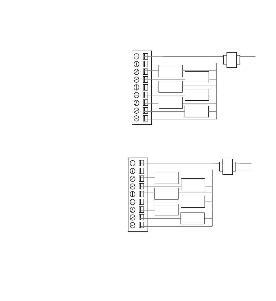
Conventional System Wiring
Note: For a heat pump system, see Section 3.6.
Connect a conventional heating system to
the zone panel as shown.
For a single stage heating and cooling
system, the 2nd stage connections are
not used.
For a system using a dual transformer,
open jumper J1 (see Configuration
section, Figure 4). Make sure the the
neutrals (common) are connected.
3.6
Heat Pump System Wiring
Connect a single or multi-stage
heat pump system to the zone panel
as shown.
A conventional thermostat may be used
with a heat pump system, however,
emergency heat will be controlled by
the panel emergency heat switch or the
optional remote emergency heat switch.
For a single-stage system, the auxiliary
heat control is not used.
• Use DIP switch 1 to select between conventional and heat pump system.
• Use DIP switch 3 for heat pump reversing valve control. Setting 0 means that the O/B terminal is
active in a cooling call. Setting B means that the O/B terminal is active in a heating call.
RH
RC
Y1
Y2
G
G2
W1
AUX
W2
O/B
C
C
HOT
1st stage
compressor
control
2nd stage
fan
control
1st stage
fan
control
1st stage
heat
control
2nd stage
compressor
control
2nd stage
heat
control
24 VAC
RH
RC
Y1
Y2
G
G2
W1
AUX
W2
O/B
C
C
HOT
1st stage
compressor
control
2nd stage
fan
control
1st stage
fan
control
aux heat /
E-heat
control
2nd stage
compressor
control
reversing
valve
24 VAC
5