Thermostat wiring, Supply air sensor wiring, Transformer wiring – Braeburn 140303 User Manual
Page 5
3.2
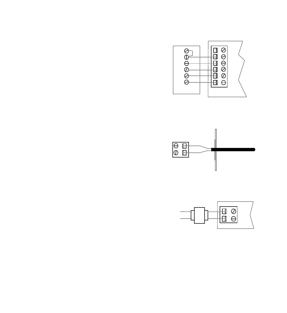
Thermostat Wiring
Install the system thermostats using the instructions
provided by the manufacturer.
Connect the thermostats to the zone panel as shown.
Notes:
• Wiring to the C terminal is required only for
thermostat power.
• E terminal at thermostat 1 controls emergency heat.
See E-Heat Switch Installation Sheet 149090 for
wiring details.
3.3
Supply Air Sensor Wiring
Install the supply air sensor in the supply air plenum at least
2-3 feet after the heat exchanger and coil. Make sure there
are no zone dampers before the supply air sensor.
Connect the supply air sensor to the zone panel as shown.
3.4
Transformer Wiring
Install the transformer using the instructions provided
by the manufacturer. Size the transformer to the damper
requirements. The zone panel has a built-in, self-resetting
fuse. The maximum damper power per panel is 35 VA at
24 VAC.
Connect the transformer to the zone panel as shown.
Note: Additional dampers or dampers with a higher current draw will require the use of a separate
slave relay.
E
R
Y
G
W
C
Rh
Rc
Y
G
W
C
Thermostat
Zone Panel
SA1
SA2
24V
24C
C
C
HOT
Dedicated
Zoning Transformer
Zone
Panel
4