Braeburn, Figure 5, Zone – Braeburn 140303 User Manual
Page 11
10
RH
RC
Y1
Y2
G
G2
W1
AUX
W2
O/B
C
SA1
SA2
Z1-PO
COM
Z1-PC
Z2-PO
COM
Z2-PC
Z3-PO
COM
Z3-PC
24V
24C
R
Y
G
W
C
R
Y
G
W
C
EMERGENCY
HEAT
ON
OFF
HI/LOW LIMIT
CUTOUT ADJUST
J2-SHORT CYCLE
PROTECTION
HEAT PUMP
DUAL FUEL
O
ELEC/HP
15
ACTIVE
ZONE1
2-STAGES
NON HP
NORMAL
REV VALVE B
FAN GAS
OPP CALL 20
LOCKOUT NONE
PRIORITY ALL
G2 W/2-ZONES
EQUIPMENT
SUPPL
Y TEMP
DAMPER 1
DAMPER 2
DAMPER 3
FLASHING WHEN NORMAL
Braeburn
3-Zone
JI REMOVE TO SEPARATE
RH AND RC TERMINAL
SUPPLY TEMP
HI TEMP
LO
TEMP
PURGE
DELAY
THERMOST
AT2
THERMOST
AT3
PWR
E
R
Y
G
W
C
THERMOST
AT1
▲
▲
4
5
6
6
1
1
1
2
3
7
6
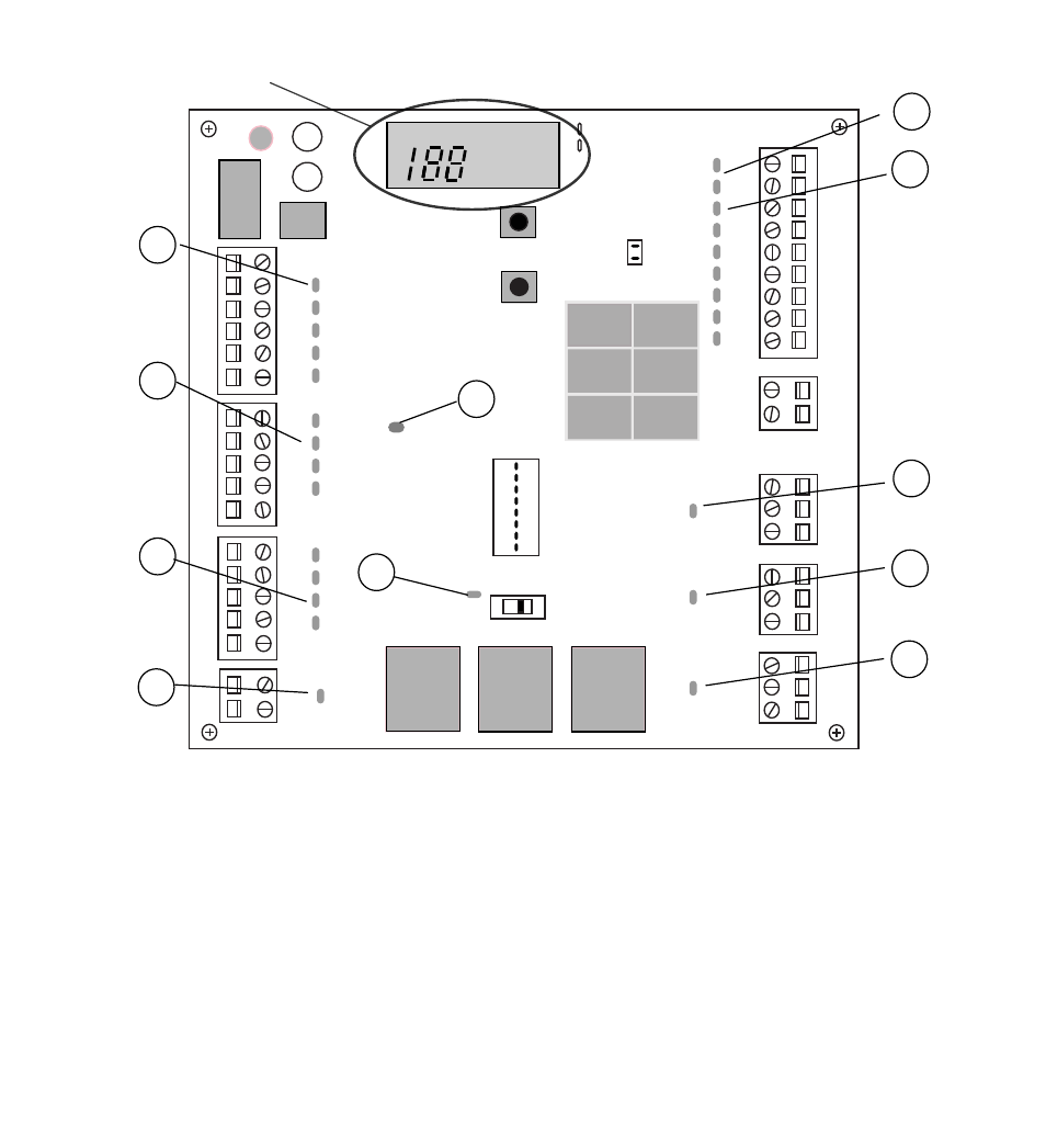
Figure 5
LED display panel
Notes:
• When no zones are calling, the panel will command all dampers to open.
• For maximum energy conservation, an adjustable purge will occur at the end of each call. No calls
will be answered until the purge is complete.
• Equipment staging is automatic based on time and plenum temperature.
• Dampers will not close and staging will not occur if the plenum temperature sensor is not connected
and functioning properly.
• No cooling calls will be answered if emergency heat is switched on.