Control panel operating procedures – AERCO BMK 3.0 LN Nat. Gas Jan 2011 User Manual
Page 33
CONTROL PANEL OPERATING PROCEDURES
1. The
DEMAND
LED status indicator will light.
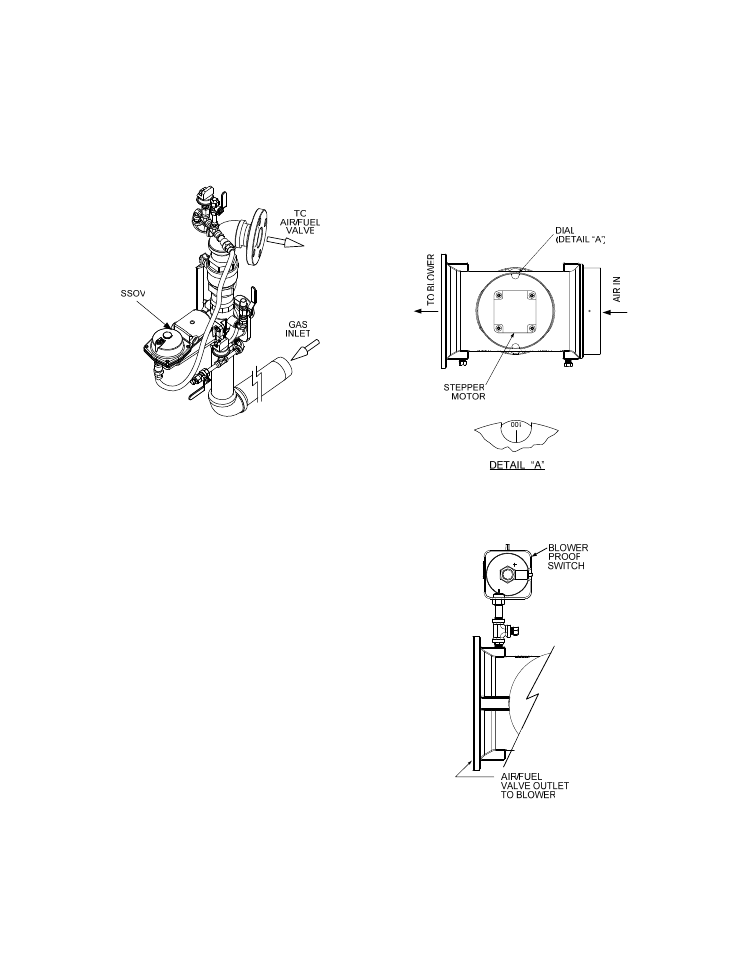
2. The unit checks to ensure that the Proof of
Closure (POC) switch in the downstream
Safety Shut-Off Valve (SSOV) is closed.
See Figure 3-3 for SSOV location.
Figure 3-3.
SSOV Location
3. With all required safety device switches
closed, a purge cycle will be initiated and the
following events will occur:
(a) The Blower relay energizes and turns
on blower.
(b) The Air/Fuel Valve rotates to the full-
open purge position and closes purge
position switch. The dial on the Air/Fuel
Valve (Figure 3-4) will read 100 to
indicate that it is full-open (100%).
(c) The VALVE POSITION bargraph will
show 100%.
4. Next, the blower proof switch on the Air/Fuel
Valve (Figure 3-5) closes. The display will
show Purging and indicate the elapsed time
of the purge cycle in seconds. The normal
(default) time for the purge cycle is 7
seconds.
5. Upon completion of the purge cycle, the
Control Box initiates an ignition cycle and
the following events occur:
(a) The Air/Fuel Valve rotates to the low-
fire ignition position and closes the
ignition switch. The dial on the Air/Fuel
Valve (Figure 3-6) will read between 25
and 35 to indicate that the valve is in
the low-fire position.
(b) The igniter relay is activated and
provides ignition spark.
(c) The gas Safety Shut-Off Valve (SSOV)
is energized (opened) allowing gas to
flow into the Air/Fuel Valve.
Figure 3-4.
Air/Fuel Valve In Purge Position
Figure 3-5.
Blower Proof Switch
3-9