Installation – AERCO BMK 3.0 LN Nat. Gas Jan 2011 User Manual
Page 16
INSTALLATION
2-4
The pr ocedures to install and c onnect b oth of
the c ondensate drains ar e pr ovided i n
paragraphs 2.6.1 and 2.6.2.
SHELL DRAIN
VALVE
EXHAUST
MANIFOLD
REAR VIEW
A
A
B
B
CONDENSATE
TRAP
DRAIN
CONNECTING
MANIFOLD
DRAIN
UNIT
FRAME
CONNECTING
MANIFOLD
DRAIN
VALVE
CONDENSATE
DRAIN PIPE
TO
CONDENSATE
TRAP
SHELL
VIEW “B - B”
VIEW “A - A”
UNIT
FRAME
EXHAUST
MANIFOLD
CONDENSATE
TRAP
DRAIN
HOSE
CLAMP
1" I.D.
HOSE
TO FLOOR
DRAIN
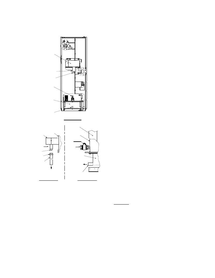
Figure 2-5
Condensate Drain Connection Location
2.6.1 Exhaust Manifold Condensate
Drain
Refer to F igure 2- 5, V iew A – A a nd install as
follows:
1. Connect a length of 1 inch I.D. hose (part no.
91030) to the drain on the exhaust manifold
and secure it in place with a hose clamp.
2. Route the hose to a nearby floor drain.
2.6.2 Connecting Manifold Condensate
Drain
The c onnecting m anifold drain pi pe s hown i n
Figure 2-5, View B – B m ust be c onnected to a
separate c ondensate drain tr ap ex ternal t o th e
unit. T his c ondensate tr ap ( part n o. 24060) is
supplied with the un it along with a trap adapter
and a 3/4” NPT x 5” long nipple. Refer to Figure
2-6 and install the trap as follows:
NOTE
The c ondensate tr ap d escribed in the
following s teps c an be installed o n t he
floor behind the unit as shown in Figure 2-
6. Ensure that the condensate trap inlet is
level with or be low t he c onnecting
manifold drain pipe. Ensure that the outlet
hose f rom the tr ap s lopes awa y ( down)
from the trap.
1. Apply Teflon tape to the threads of the 3/4” x
5” long nipple provided with the boiler.
2. Attach t he 3/4” N PT nip ple b etween th e
condensate trap inl et and the tr ap ada ptor
(Figure 2-6).
3. Attach another 3/4” NPT nipple (not sup-
plied) to the condensate trap outlet on the
lower part of the trap.
4. Connect the condensate trap and adaptor to
the connecting manifold drain pipe. Position
the trap so it is level and then tighten the
thumb screw on the adaptor.
5. Place a suitable support under the
condensate trap to maintain the trap in the
level position.
6. Connect a length of 1” I.D. polypropylene hose
to the outlet side of the condensate trap and
route it to a nearby floor drain.
If desired, a Tee fitting may be used to connect the
two drain hoses from the exhaust manifold and the
outlet side of the of the condensate trap attached to
the connecting manifold.
If a floor drain is n ot available, a condensate pump
can be u sed to r emove the condensate to drain.
The m aximum co ndensate flow r ate i s 20 GPH.
The condensate dr ain t rap, associated fittings and
drain lines m ust be removable fo r routine
maintenance.