Installation – AERCO BMK 3.0 LN Nat. Gas Jan 2011 User Manual
Page 18
INSTALLATION
2-6
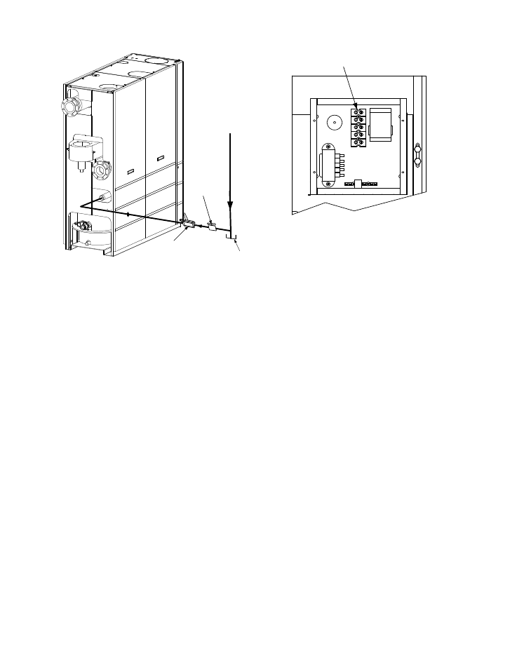
NATURAL
GAS
SUPPLY
DIRT
TRAP
2" MANUAL
SHUTOFF
VALVE
MANDATORY
REGULATOR FOR
MASSACHUSSETTS
INSTALLATIONS ONLY
Figure 2-7
Manual Gas Shut-Off Valve Location
2.7.4 IRI Gas Train Kit
The IRI gas tr ain is a n opti onal g as tr ain
configuration which is required in some areas for
code c ompliance or f or ins urance purposes.
The IRI gas train is factory pre-piped and wired.
See Appendix F, Drawing AP-A-803 for details.
2.8 AC ELECTRICAL POWER WIRING
The AERCO Be nchmark 3.0 E lectrical Po wer
Wiring Guide, GF-3060, must be consulted prior
to c onnecting a ny AC po wer wiring t o th e u nit.
External AC po wer connections are made to the
unit inside the Power Box on the f ront pa nel of
the u nit. Remove the f ront door of the unit to
access the P ower Box m ounted directly above
the Co ntrol Box . Loosen the f our Po wer B ox
cover scre ws a nd re move co ver t o a ccess t he
AC t erminal c onnections i nside the P ower Box
(Figure 2-8).
NOTE
All elec trical c onduit a nd hardware m ust
be ins talled s o that it do es not inter fere
with the removal of any unit covers, inhibit
service/maintenance, or pr event ac cess
between the unit and w alls or ano ther
unit.
UPPER RIGHT CORNER OF FRONT PANEL
TERMINAL BLOCK
Figure 2-8
AC Input Terminal Block Location
2.8.1 Electrical Power Requirements
The AERCO Be nchmark 3 .0 Bo iler is ava ilable
in two different AC power configurations:
•
208 VAC/3-Phase/60 @20 amps
•
460 VAC/3-Phase/60 Hz @ 15 amps
Each of the power configurations utilize a Power
Box with a t erminal b lock that m atches the
configuration ordered. The two different terminal
block configurations are shown in Figure 2-9. A
wiring d iagram s howing t he r equired AC po wer
connections is provided on the front cover of the
Power Box.
Each B enchmark 3.0 Boil er must be c onnected
to a d edicated el ectrical circuit. NO O THER
DEVICES SHO ULD B E O N THE SAM E
ELECTRICAL CIRCU IT AS T HE BENCHMARK
BOILER. A m eans f or dis connecting AC p ower
from the unit ( such as a service switch) must be
installed n ear th e un it f or normal oper ation and
maintenance. All e lectrical c onnections s hould
be m ade i n ac cordance with th e Nat ional
Electrical Code and/or with any applicable local
codes.
For elec trical p ower wiring diagr ams, s ee the
AERCO Benchmark 3.0 El ectrical Power Wiring
Guide, (GF-3060).