Gf-123, Benchmark 2.0ln low nox boiler – AERCO BMK 2.0 LN October 2012 User Manual
Page 87
GF-123
Benchmark 2.0LN Low NOx Boiler
Chapter 7
OMM-0046_0F
I
nstallation, Operation and Maintenance Manual
Maintenance
PR1 10/17/12
AERCO International Inc.● 100 Oritani Dr. ● Blauvelt, NY 10913. ● Ph: 800-526-0288
Page 87 of 172
IMPORTANT
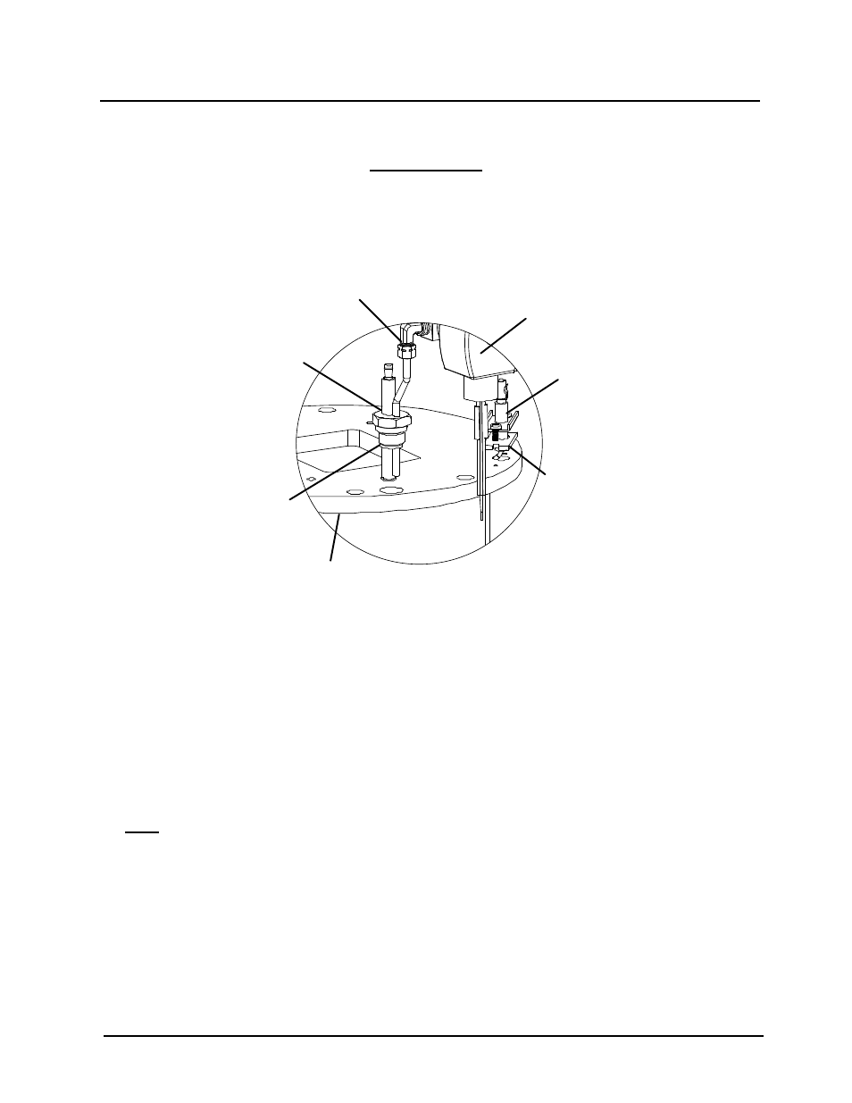
Prior to removing the igniter-injector, note the position of the gas injector
tube relative to the burner plate and blower. This is necessary to ensure
that the igniter injector is reinstalled in the proper orientation when it is
reconnected to the staged ignition assembly.
STAGED
IGNITION
ASSEMBLY
FLAME
DETECTOR
IGNITOR-
INJECTOR
BURNER
PLATE
COMPRESSION
FITTING & ELBOW
FLAME
DETECTOR
GASKET
INDEXING
WASHERS
(QTY = 0-3
AS REQ’D)
Figure 7-2: Igniter-Injector & Flame Detector Mounting Details
5. Next, loosen and remove the igniter-injector from the burner plate using a 1" open-end
wrench.
6. Check the igniter-injector for evidence of erosion or carbon build-up. If there is evidence of
substantial erosion or carbon build-up, the igniter-injector should be replaced. If carbon
build-up is present, clean the component using fine emery cloth. Repeated carbon build-up
is an indication that the combustion settings of the unit should be checked. Refer to Chapter
4 for combustion calibration procedures.
7. Prior to reinstalling the igniter-injector, a high temperature, conductive, anti-seize compound
must be applied to the threads.
NOTE
If a replacement igniter-injector (part no. 58023) is being installed, a
compression nut containing a built-in ferrule will be included with the
replacement part. If needed, three indexing washers are also included
These washers may be needed to properly position the gas injector tube of
the igniter-injector within the 120° angle range shown in Figure 7-3.