10 i/o box connections, 1 outdoor sensor in (1), Benchmark 2.0ln low nox boiler – AERCO BMK 2.0 LN October 2012 User Manual
Page 26: Gf-123
Chapter 2
Benchmark 2.0LN Low NOx Boiler
GF-123
Installation
Installation, Operation and Maintenance Manual
OMM-0046_0F
Page 26 of 172
AERCO International Inc.● 100 Oritani Dr. ● Blauvelt, NY 10913. ● Ph: 800-526-0288 PR1 10/17/12
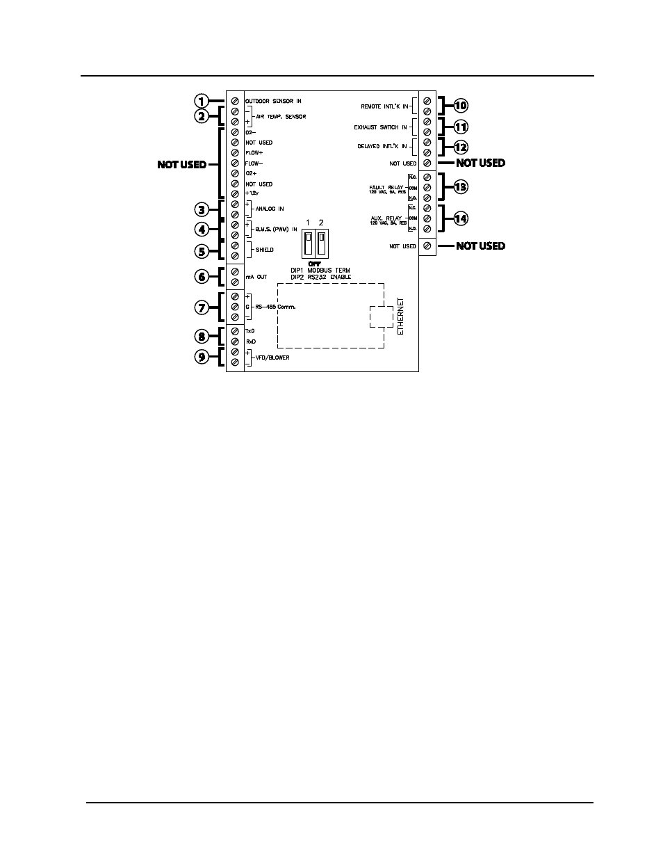
Figure 2-10. I/O Box Terminal Locations and Functions
2.10 I/O BOX CONNECTIONS
The types of input and output signals and devices to be connected to the I/O Box terminals
shown in Figure 2-10 are described in the following paragraphs.
NOTE
Older I/O PCBs are wired the same as new ones, even if silk-screen
designations differ.
NOTE
DO NOT make any connections to the I/O Box terminals labeled “NOT
USED”. Attempting to do so may cause equipment damage.
2.10.1 OUTDOOR SENSOR IN
(1)
An outdoor air temperature sensor (AERCO Part No. 122790) will be required primarily for the
Indoor/Outdoor reset mode of operation. It can also be used with another mode if it is desired to
use the outdoor sensor enable/disable feature. This feature allows the boiler to be enabled or
disabled based on the outdoor air temperature.
The factory default for the outdoor sensor is DISABLED. To enable the sensor and/or select an
enable/disable outdoor temperature, see the Configuration menu in Chapter 3.
The outdoor sensor may be wired up to 200 feet from the boiler. It is connected to the
OUTDOOR SENSOR IN and SENSOR COMMON terminals in the I/O Box (see Figures 2-9 and
2-10). Wire the sensor using a twisted shielded pair wire from 18 to 22 AWG. There is no
polarity to observe when terminating these wires. The shield is to be connected only to the