10 purge switch open during purge, 11 ignition switch open during ignition, Benchmark 2.0ln low nox boiler – AERCO BMK 2.0 LN October 2012 User Manual
Page 82: Gf-123
Chapter 6
Benchmark 2.0LN Low NOx Boiler
GF-123
Safety Device Tests
Installation, Operation and Maintenance Manual
OMM-0046_0F
Page 82 of 172
AERCO International Inc.● 100 Oritani Dr. ● Blauvelt, NY 10913. ● Ph: 800-526-0288 PR1 10/17/12
11. Replace the wire on the SSOV and press the CLEAR button. The unit should restart.
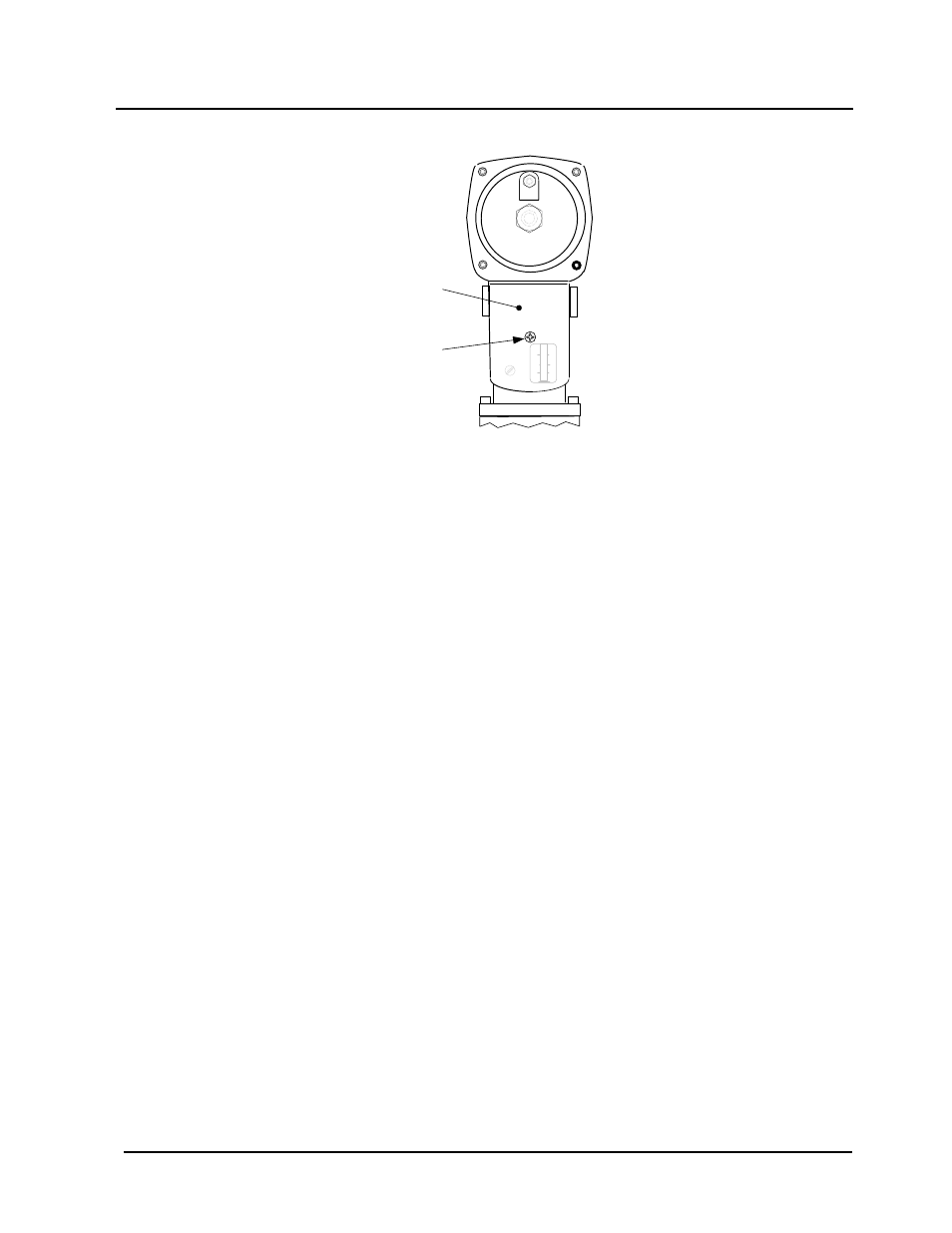
ACTUATOR
COVER
SCREW
SSOV
ACTUATOR
COVER
Figure 6-4: SSOV Actuator Cover Location
6.10 PURGE SWITCH OPEN DURING PURGE
The Purge Switch (and Ignition Switch) is located on the Air/Fuel Valve. To check the switch,
proceed as follows:
1. Set the unit’s ON/OFF switch to the OFF position. Place the unit in manual mode and set the
valve position between 25% and 30%.
2. Remove the Air/Fuel Valve cover by rotating the cover counterclockwise to unlock it and
then lift up (see Figure 6-5).
3. Remove one of the two wires (#171 or #172) from the Purge Switch (Figure 6-6).
4. Initiate a unit start sequence.
5. The unit should begin it’s start sequence, then shut down and display PRG SWITCH OPEN
DURING PURGE.
6. Replace the wire on the Purge Switch and depress the CLEAR button. The unit should
restart.
6.11 IGNITION SWITCH OPEN DURING IGNITION
The Ignition Switch (and the Purge Switch) is located on the Air/Fuel Valve. To check the
switch, proceed as follows:
1. Set the unit’s ON/OFF switch to the OFF position.
2. Place the unit in Manual Mode and set the valve position between 25% and 30%.
3. Remove the Air/Fuel Valve cover (Figure 6-5) by rotating the cover counterclockwise to
unlock and lift up to remove.
4. Remove one of the two wires (#169 or #170) from the Ignition Switch (Figure 6-6).
5. Initiate a unit start sequence.
6. The unit should begin its start sequence and then shut down and display IGN SWITCH
OPEN DURING IGNITION.
7. Replace the wire on the Ignition Switch and press the CLEAR button. The unit should
restart.