Spanning tree protocol in a network, Spanning tree protocol parameters – Cabletron Systems SmartSTACK ELS100 User Manual
Page 92
78 Spanning Tree Concepts
ELS100-24TX
Spanning Tree Protocol in a Network
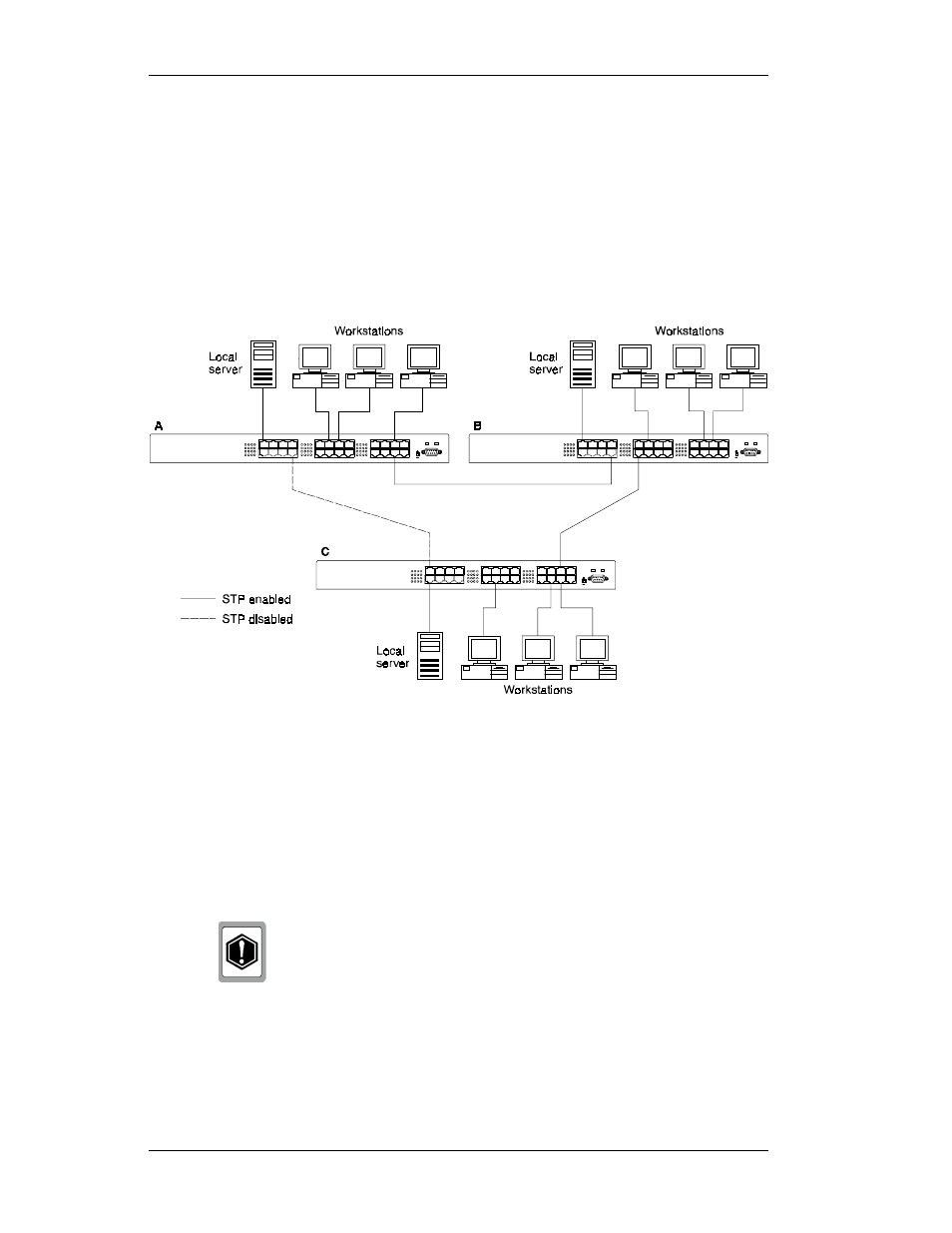
Figure B-1 illustrates the use of three ELS100-24TX switches to establish
an effective Spanning Tree configuration. Switches A, B and C are
connected together in a redundant topology (more than one path between
two points). If the connection between A and B goes down, the link
between A and C becomes active, thereby establishing a path between A
and B through switch C. Additionally, if the connection between B and C
goes down, the link between A and C becomes active, establishing a path
between B and C through switch A.
Figure B-1. Spanning Tree Using ELS100-24TX Switches
Spanning Tree Protocol Parameters
Several configuration parameters control the operation of the Spanning
Tree Protocol. Table B-1 describes the parameters and lists the
ELS100-24TX switch default settings for each parameter.
You can cause serious network performance degradation
if you do not fully understand Spanning Tree concepts.
Be sure to consult personnel experienced with this
process prior to configuring Spanning Tree parameters.