Rear panel – Cabletron Systems SmartSTACK ELS100 User Manual
Page 19
9032579-03
Product Overview 5
Table 1-2. Port LEDs Defined
Rear Panel
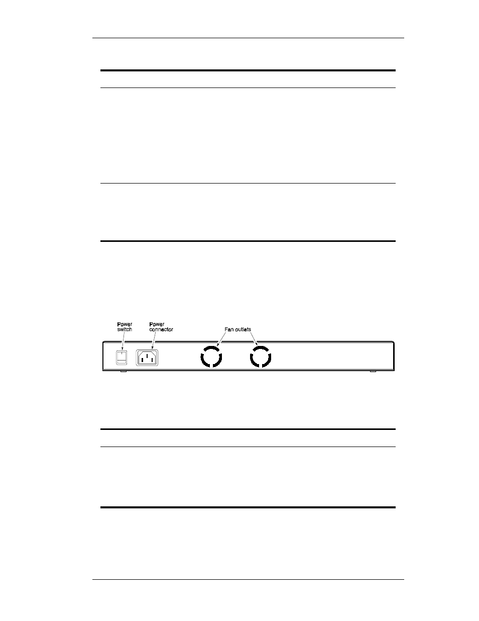
Figure 1-4 shows the ELS100-24TX rear panel and Table 1-3 defines the
rear panel components.
Figure 1-4. ELS100-24TX Rear Panel
Table 1-3. Rear Panel Components
Name
Function
Default
Configuration
Link LED On: Indicates a valid connection (link) on the
associated port.
Link LED Off: Indicates no link on the associated port.
Activity LED flashing: Indicates the presence of transmit and/or
receive activity.
Activity LED Off: Indicates the absence of transmit or receive
activity.
LED mode
button pressed
Speed LED On: Indicates the port is in the 100Base-TX mode.
Speed LED Off: Indicates the port is in the 10Base-T mode.
Duplex LED On: Indicates the port is in the full duplex mode.
Duplex LED Off: Indicates the port is in the half duplex mode.
Name
Function
Power Connector
Provides AC power to the switch.
Power Switch
Allows you to turn the switch power on and off.
Fan Outlets
Air exit vents through which internal fans discharge air
for ventilation purposes.