Cautions on wiring for each unit, Contact protection, Part names and functions – KEYENCE KV Series User Manual
Page 3: Terminal layout drawings and i/o circuit diagrams, Kv series basic unit-im_e, Wiring procedures for basic units, Wiring for an ac type basic unit, Wiring for a dc type basic unit, Cautions on wiring for i/o units, Terminal
3
KV Series Basic Unit-IM_E
This section describes cautions to keep in mind when wiring is performed for I/O units. Be
sure to read this section before starting wiring.
Wiring procedures for basic units
The wiring procedures for basic units are described below.
.
Wiring for an AC type basic unit
For an AC type basic unit, perform the wiring as shown in the figure below.
Wiring for a DC type basic unit
For a DC type basic unit, perform the wiring as shown in the figure below.
Cautions on wiring for I/O units
When performing wiring for an I/O unit, pay strict attention to the following contents.
• Separate input lines from output lines in wiring.
• If the wiring for power is located near I/O signal lines, a malfunction may occur caused
by the effects of a high voltage and large current.
• Keep I/O signal lines away from the power wiring by at least 100 mm.
• Separate 24VDC I/O lines from 100 VAC and 200 VAC lines.
• When using pipes for wiring, make sure that the pipes are securely grounded.
When I/O signal lines cannot be separated from the wiring for power
In such a case, perform grounding on the KV side using batch-shielded cables. (In some
environments, grounding should be performed on the reverse side of the KV.)
Terminal
The terminal screws used are M3. When performing wiring with crimp-style terminals, use
the following ones.
Cautions on grounding
Because the KV Series is constructed to be sufficiently resistant to noise, it can usually be
used without being grounded. However, when the KV Series is used in an environment with
a lot of noise, grounding is required. In such a case, pay strict attention to the following
contents.
• Perform completely grounding for each individual unit. In this case, the ground
resistance should be 100 ¾ or less.
• If individual grounding is not possible, perform common grounding. In this case, the
length of each grounding cable should be equal.
If inductive loads such as clutches, motors, and solenoids are used, a rush current may flow
when the load power supply is turned on, or a counter electromotive voltage may be
generated when the load power supply is shut down. The rush current and the counter
electromotive voltage can contribute considerably to shortening the service life of the
contacts. To prevent this from happening, provide a contact protection circuit.
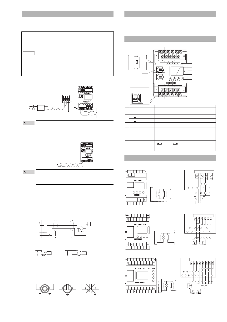
KV-10AR/DR (Relay output type)
Terminal layout drawing
Output circuit diagram
KV-16AR/DR (Relay output type)
Terminal layout drawing
Output circuit diagram
KV-24AR/DR (Relay output type)
Terminal layout drawing
Output circuit diagram
Cautions on Wiring for Each Unit
•
Turn off the power before starting wiring.
•
For the installation position, select a location whose ambient
temperature is 0 to +50°C (32 to 122°F) (No freezing), whose
ambient humidity is 35 to 85% RH (No condensation), and one
which is not subject to drastic temperature changes.
•
If the 24 V DC + output terminal and the 24 V DC - output terminal
are switched, the power supply unit and connected units may be
damaged. Never switch them.
•
Be sure that the sum of the current consumption of all connected
units does not exceed the output capacity of the service power
supply. If the system is operating in an overload status, the internal
circuits may generate heat or be damaged. To recover from an
overload status, disconnect some of the connected units.
•
Never connect the DC output of any other power supply, either in
serial or parallel, to the 24 V DC output terminals. If the DC output is
connected, the power supply unit may be damaged.
•
Connect an insulating transformer (1:1) or noise filter to reduce line noise.
•
Use twisted cables to reduce induction effects.
•
When using a basic unit in a location with a lot of noise, the noise
may be reduced by using completely grounding the basic unit.
•
Connect the power supply to the power supply input terminals with
24 VDC output, which offers a sufficient margin of power capacity.
Usually, the sum of the current consumption of all connected units
multiplied by 1.5 or more is required for the power capacity.
•
To reduce line noise, insert a ferrite core.
NOTICE
0
1
2
3
0
1
2
3
4
5
5ch
0ch
C1
001
002
003
004
005
C2
KV-10AR
500
24V-OUT-OV
C3
C4
503
501
502
000
IN
OUT
EYENCE
24 V DC service
power supply
(supplied from
outside)
Grounding
The power input
terminals at the lower
side of the unit
Insulating transformer,
noise filter, etc.
Breaker
AC100 to
240 V
±10%
KV-10AR
Point
KV-10DR
0
1
2
3
0
1
2
3
4
5
5ch
0ch
C1
001
002
003
004
005
C2
KV-10DR
500
24V-IN-OV
C3
C4
503
501
502
000
IN
OUT
EYENCE
24 V DC external power supply
Breaker
Point
RL
24 V DC
KV
Sensor
Ground
Shielded cable
Input
Output
M3
6.0 maximum
KV
KV
A = B
A > B
A < B
B
B
A
KV
A
Completely grounding
Contact Protection
Part Names and Functions
Terminal layout drawings and I/O circuit diagrams
0
1
2
3
4
5
0
1
2
3
4
5
6
7
8
9
5ch
0ch
C1
001
003
005
007
009
008
006
004
002
500
KV-16AR
C3
24V-OUT-OV
C4
503
505
501
502
504
000
IN
OUT
EYENCE
24V
5V
INPUT
VOLT
AC100V-240V
0.5A 50/60Hz
L
~
N
.
o
N
e
m
a
N
n
o
i
t
c
n
u
F
1
e
t
a
l
p
l
a
n
i
m
r
e
t
t
u
p
n
I
.
)
t
u
p
n
i
V
5
o
t
d
e
g
n
a
h
c
e
b
n
a
c
7
0
0
o
t
0
0
0
(
e
t
a
l
p
l
a
n
i
m
r
e
t
t
u
p
n
i
C
D
V
4
2
2
e
t
a
l
p
l
a
n
i
m
r
e
t
t
u
p
t
u
O
Output terminal plate. Pulse output function is built in 500 to 502 (in transistor output type only).
k
6
.
1
A
Ω
.
)
r
e
v
i
r
d
r
o
t
o
m
a
t
c
e
n
n
o
c
o
t
(
2
0
5
R
n
i
t
li
u
b
s
i
r
o
t
s
i
s
e
r
g
n
i
t
i
m
il
t
n
e
r
r
u
c
3
l
a
n
i
m
r
e
t
t
u
p
n
i
r
e
w
o
P
)
)
P
(
T
D
/
R
D
-
V
K
(
.
C
D
V
4
2
s
e
il
p
p
u
S
l
a
n
i
m
r
e
t
t
u
p
t
u
o
r
e
w
o
P
)
)
P
(
T
A
/
R
A
-
V
K
(
t
i
n
u
e
h
t
f
o
e
d
i
s
r
e
w
o
l
e
h
t
n
o
s
l
a
n
i
m
r
e
t
t
u
p
n
i
r
e
w
o
p
e
h
t
o
t
C
A
V
0
4
2
o
t
0
0
1
s
e
il
p
p
u
S
.
l
a
n
i
m
r
e
t
C
D
V
4
2
e
h
t
m
o
r
f
n
e
k
a
t
e
b
o
t
r
e
w
o
p
e
c
i
v
r
e
s
s
w
o
ll
a
d
n
a
4
s
p
m
a
l
r
o
t
a
c
i
d
n
i
t
u
p
n
I
.
N
O
t
a
p
u
s
t
h
g
il
p
m
a
l
h
c
a
E
.
s
u
t
a
t
s
t
u
p
n
i
e
t
a
c
i
d
n
I
5
s
p
m
a
l
r
o
t
a
c
i
d
n
i
t
u
p
t
u
O
.
N
O
t
a
p
u
s
t
h
g
il
p
m
a
l
h
c
a
E
.
s
u
t
a
t
s
t
u
p
t
u
o
e
t
a
c
i
d
n
I
6
)
e
d
i
s
n
o
d
e
d
i
v
o
r
p
(
r
o
t
c
e
n
n
o
C
.
t
i
n
u
n
o
i
s
n
a
p
x
e
n
a
t
c
e
n
n
o
c
o
t
d
e
s
U
7
w
o
d
n
i
w
s
s
e
c
c
A
s
a
s
r
e
t
n
u
o
c
d
n
a
s
r
e
m
i
t
f
o
s
e
u
l
a
v
t
e
s
d
n
a
t
n
e
r
r
u
c
e
h
t
e
g
n
a
h
c
d
n
a
o
t
r
e
f
e
r
o
t
d
e
s
U
.
s
e
i
r
o
m
e
m
a
t
a
d
f
o
s
t
n
e
t
n
o
c
e
h
t
s
a
ll
e
w
.
s
u
t
a
t
s
n
o
i
t
a
r
e
p
o
e
h
t
s
e
t
a
c
i
d
n
i
r
o
l
o
c
t
h
g
il
k
c
a
b
e
h
T
s
u
t
a
t
s
r
o
r
r
E
:
d
e
r
g
n
i
h
s
a
l
F
e
d
o
m
M
A
R
G
O
R
P
:
d
e
r
n
i
t
i
L
e
d
o
m
N
U
R
:
n
e
e
r
g
n
i
t
i
L
8
s
y
e
k
g
n
i
t
t
e
S
.
w
o
d
n
i
w
s
s
e
c
c
a
e
h
t
o
t
g
n
i
r
r
e
f
e
r
e
li
h
w
.
c
t
e
,
s
e
u
l
a
v
t
n
e
r
r
u
c
e
g
n
a
h
c
d
n
a
o
t
r
e
f
e
r
o
t
d
e
s
U
9
h
c
t
i
w
s
r
o
t
c
e
l
e
s
e
g
a
t
l
o
v
t
u
p
n
I
.
t
i
n
u
c
i
s
a
b
e
h
t
f
o
e
g
a
t
l
o
v
t
u
p
n
i
e
h
t
s
e
g
n
a
h
C
t
u
p
n
i
V
5
:
t
u
p
n
i
V
4
2
:
0
1
A
t
r
o
p
n
o
i
t
a
c
i
n
u
m
m
o
C
Modular connector for connecting a personal computer, handheld programmer, or operator panel.
1
1
B
t
r
o
p
n
o
i
t
a
c
i
n
u
m
m
o
C
Modular connector for connecting a personal computer, handheld programmer, or operator panel.
6. Connector (provided on side)
2. Output terminal block
3. Power input terminal
10.Communication
port A
9. Input voltage selector
switch
Provided on side
1. Input terminal block
4. Input indicator lamps
5. Output indicator lamps
7. Access window
11. Communication
port B
(Power input terminals for
AC power types are provided
on the lower
side of the
unit.)
8. Setting keys
000 001 002 003 004 005
24V 0V 500 C3 C4 503
C1 C2
501 502
500
C3
C4
501 to 503
503
502
C4
501
C3
500
0V
24V
• C3 and C4 are each independent.
In
te
rn
a
l ci
rc
u
it
Internal circuit
C4
501
C3
503
505
500
502
504
0V
24V
C1 001 003 005 007 009
000 002 004 006 008
24V 0V C3 C4 503 505
500 501 502 504
500 to 501
C3
C4
502 to 505
• C3 and C4 are each independent.
Inter
na
l c
ir
c
uit
Internal circuit
C1 001 003 005 007 009 011 013 015
000 002 004 006 008 010 012 014
24V 0V C3 C4 C5 C6 505 507
500 501 502 503 504 506
C6
503
C5
505
507
502
504
506
C4
C3
501
500
0V
24V
500
501
502 to 503
504 to 507
C3
C4
C5
C6
• C3 to C6 are each independent.
Inte
rn
al c
ir
c
uit
Internal circuit