Ac power specifications, Installation environment, Installation position – KEYENCE KV Series User Manual
Page 2: Installation procedure, Kv series basic unit-im_e, Kv series operation at power interruption, Installation direction, Distance between adjacent panels/equipment, Output specifications, Drop in supply voltage
2
KV Series Basic Unit-IM_E
Output specifications
(relay output):
KV-10AR/DR, KV-16AR/DR, KV-24AR/DR, and KV-40AR/DR
(transistor output): KV-10AT(P)/DT(P), KV-16AT(P)/DT(P), KV-24AT(P)/DT(P),
and KV-40AT(P)/DT(P)
*
Includes the internal current consumption and current consumption of expansion units.
KV Series operation at power interruption
Drop in supply voltage
• When the supply voltage drops, the KV Series stops operating and the output turns off.
Detection of instantaneous power interruption
• An AC type basic unit continues operating against instantaneous power interruption of
less than 40 ms. A DC type basic unit continues operating against instantaneous power
interruption of less than 2 ms.
• An AC type basic unit may or may not accept instantaneous power interruption of 40 ms
or more. A DC type basic unit may or may not accept instantaneous power interruption
of 2 ms or more.
• When accepting instantaneous power interruption, a basic unit stops operating and the
output turns off.
Automatic recovery
• Once the supply voltage recovers, the KV Series restarts operation automatically.
Installation environment
• Locations exposed to direct sunlight
• Locations whose ambient temperature is outside the allowable range of 0 to +50°C (32
to 122°F) (No freezing)
• Locations whose ambient humidity is outside the allowable range of 35 to 85% RH (No
condensation)
• Locations subject to drastic temperature change where condensation may occur
• Locations with corrosive or flammable gases
• Locations with excessive dust, salt, iron powder, or soot
• Locations subject to direct vibrations and impacts
• Locations subject to splashes of water, oil, chemicals, etc.
• Locations where a strong magnetic or electrical field is generated
.
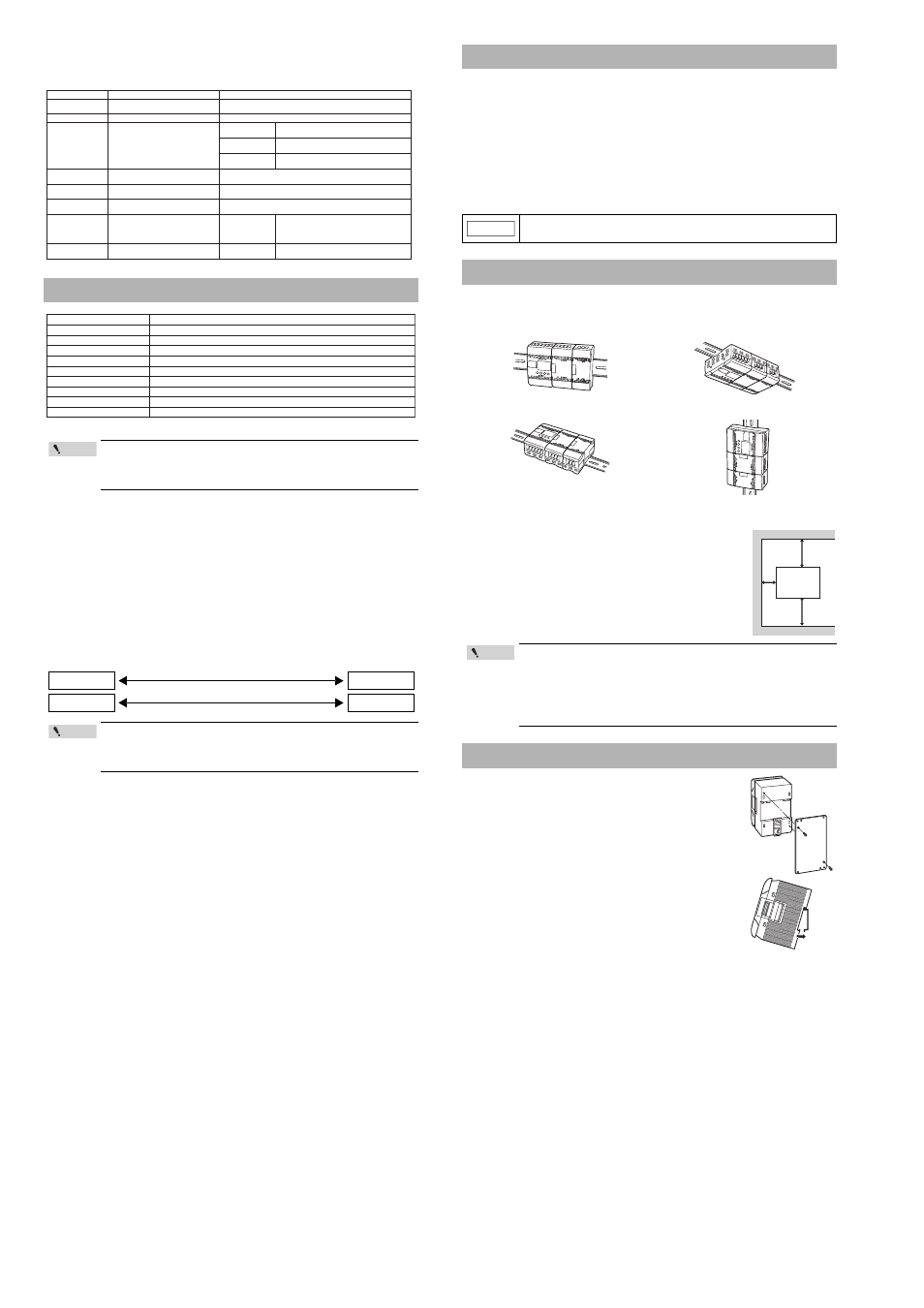
Installation direction
When attaching a unit inside a panel, install the unit so that the front face (equipped with the
access window, communication ports, etc.) faces front or upward.
Distance between adjacent panels/equipment
When installing a unit, keep the distances shown on the right
between the panel or equipment so that the power supply can
release heat.
This section describes how to attach a connected unit directly to a
panel, to a DIN rail, or to a DIN rail with an expansion unit spacer.
Attaching a unit directly to a panel
Attach a metal fixture for screw tightening to a KV Series basic unit
with set screws. Then, attach the basic unit with a metal fixture
directly to the panel.
Attaching a unit to a DIN rail
Hang an upper claw of a KV Series basic unit to the upper side of
the DIN rail, and press the basic unit onto the DIN rain until a click
sound is heard.
Removing a unit from a DIN rail
Pull a lower claw of a KV Series basic unit downward from the
front direction using a screwdriver, and then remove the basic unit
from the DIN rail.
AC Power Specifications
The maximum output capacity available with the AC type service
power output is the output capacity of each basic unit subtracted by
the internal current consumption of the basic unit, connected
expansion units, and connected peripheral units.
If the supply voltage increases gradually or drops, the KV Series may repeat
operation and then stop. If problems continue to occur with equipment and
other operations from repetitive starts and stops, provide a protection circuit
so that the output shuts down until the voltage reaches the rated value.
50 m
Ω or less
ON resistance
Item
Specifications (relay output):
Specifications (transistor output):
Rated load
250 V AC/30 V DC, 2 A (inductive load),
4 A (resistive load)
30 V DC, 0.1 A (500 to 502), 0.3 A (others)
Peak load current
5A
0.2 A (500 to 502), 1 A (others)
Maximum
voltage at OFF
30 V DC
Leak current in
OFF status
100 µA or less
Residual voltage
in ON status
0.8 V or less
Rising operating
time (OFF
→ ON)
10 ms or less
10 µs or less (500 to 502) (at 5 to 100 mA),
20 µs or less (others) (at 10 to 300 mA)
Falling operating
time (ON
→ OFF)
10 ms or less
10 µs or less (500 to 502) (at 5 to 100 mA),
100 µs or less (others) (at 10 to 300 mA)
Common method
Each common terminal is
independent.
1 common
Relay service life
Electrical service life: 100,000 times
or more (20 times/min)
Mechanical service life: 20,000,000
times or more
Output
frequency
50 kHz (500 to 502)
Relay
replacement
Not allowed
Built-in serial
resistance
1.6 k
Ω 1/2 W (R500 to R502)
m
e
t
I
ns
o
i
t
a
c
i
f
i
c
e
p
S
d
o
h
t
e
M
d
o
h
t
e
m
g
n
i
h
c
t
i
w
S
e
s
i
o
n
e
l
p
p
i
R
s
s
e
l
r
o
p
-
p
V
m
0
4
2
n
o
i
t
p
m
u
s
n
o
c
t
n
e
r
r
u
c
r
e
w
o
p
C
A
A
7
.
0
:
x
A
0
4
-
V
K
A
4
.
0
:
x
A
4
2
-
V
K
A
5
.
0
:
x
A
6
1
-
V
K
A
4
.
0
:
x
A
0
1
-
V
K
e
g
a
t
l
o
v
t
u
p
n
i
r
e
w
o
p
C
A
(
C
A
V
0
4
2
o
t
0
0
1
±
)
%
0
1
r
o
t
c
a
f
r
e
w
o
p
C
A
%
0
6
e
g
a
t
l
o
v
t
u
p
t
u
O
C
D
V
4
2
±
%
0
1
y
t
i
c
a
p
a
c
t
u
p
t
u
O
A
7
.
0
:
x
A
0
4
-
V
K
A
6
.
0
:
x
A
4
2
-
V
K
A
6
.
0
:
x
A
6
1
-
V
K
A
4
.
0
:
x
A
0
1
-
V
K
n
o
i
t
p
m
u
s
n
o
c
r
e
w
o
P
W
4
2
:
x
A
0
4
-
V
K
W
1
2
:
x
A
4
2
-
V
K
W
1
2
:
x
A
6
1
-
V
K
W
4
1
:
x
A
0
1
-
V
K
e
s
u
f
d
e
s
U
e
p
y
t
g
n
i
t
l
e
m
-
t
s
a
F
:
s
c
i
t
s
i
r
e
t
c
a
r
a
h
C
,
A
5
1
.
3
:
t
n
e
r
r
u
c
d
e
t
a
r
,
C
A
V
0
4
2
:
e
g
a
t
l
o
v
d
e
t
a
R
Point
Instantaneous power interruption: Less than 40 ms
Instantaneous power interruption: 40 ms or more
Rated voltage
Rated voltage
Rated voltage
Rated voltage
Point
Installation Environment
Units are made of synthetic resin. If the unit surface touches a solvent with a strong
dissolving force, it could melt. Keep such solvents away from the units.
Installation Position
•
If the temperature inside the panel exceeds 50°C (122°F), which is
specified as the maximum ambient operating temperature, then
install heat exchangers, etc. to reduce the temperature.
•
Ensure sufficient ventilation space so that the power supply can
release heat.
•
Never install a unit just above any equipment which generates a lot
of heat.
Installation Procedure
NOTICE
Front installation
Correct
Incorrect
* See page 3.
Installation on ceiling
Upward installation
Vertical installation
Correct
Incorrect
20 mm
20 mm
10 mm
Point