Connections, Installation, Connector pin assignment – KEYENCE BL-700 Series User Manual
Page 3: Wiring of power supply, Input/output wiring, Wiring for rs-232c, Operating environment
3
Connections
* When the exclusive power supply is used, refer to the user’s manual.
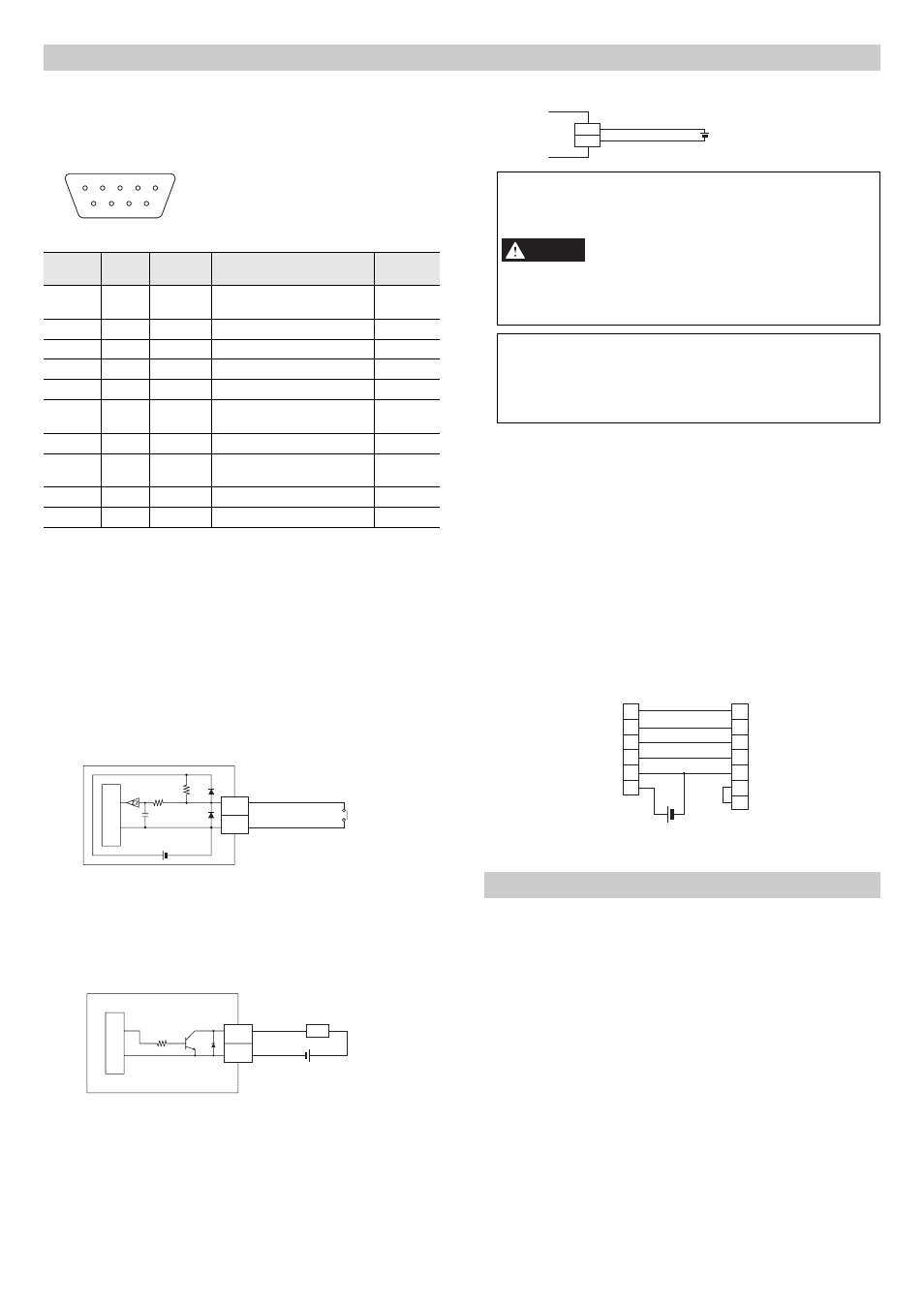
Connector Pin Assignment
The pin assignment of the BL-700 connector is as listed below.
Wiring of Power supply
Pin No.
Wire
Color
Code
Description
Signal
direction
Connector
housing
Shield
FG
Frame ground
-
1
Yellow
TIM
Timing input
Input
2
Brown
RD(RXD)
RS-232C receive data
Input
3
Purple
SD(TXD)
RS-232C send data
Output
4
White
OK
OK output
Output
5
Black
GND(SG)
Ground (common ground for
each signal)
-
6
Gray
NG
NG output
Output
7
Pink
RS(RTS)
RS-232C request to send
(normally ON)
Output
8
Blue
CS(CTS)
RS-232C clear to send
Input
9
Red
+5V
+5VDC power supply
Input
4
5
3 2 1
9 8 7 6
D-sub9 pin (female)
DTE (terminal) definition
#4-40 screw (male)
• Never connect + and - terminals of the power
supply in the reverse directions, to prevent mal-
functions.
• Use regulated 5VDC ±5% power supply. Use of
a power supply exceeding the range may
cause a damage.
• Do not extend the power supply cable.
Otherwise, voltage drop may occur, adversely
affecting operation of the BL-700.
• Use the power supply that provides Class 2 output defined in
NFPA 70 (NEC: National Electrical Code) when using this prod-
uct as an UL certified product.
• Use the Limited Power Source defined in UL/IEC60950-1 to
comply with UL/IEC60950-1.
DC5V
+5V
GND
BL-700
9
5
+
CAUTION
Input/Output Wiring
z Wiring of timing input
The timing input starts scanning by the BL-700 (turns the laser on).
Use the no-voltage input for the timing input (use the negative logic
when the TTL input is used).
z Wiring for OK/NG output
Use the OK/NG output for checking by comparing with the preset
data (when preset data is not registered, to indicate if a bar code is
read or not).
The NPN open collector output is used.
Wiring for RS-232C
When a personal computer is connected, arrange the wiring as
shown below.
z Connecting the computer with 9-pin
Installation
Operating Environment
This unit is a precision equipment. So, pay attention to the installation
place and avoid the following places:
z Places subject to direct sunshine or temperature exceeding a
range between 0 to +40
qC (32 to 104qF). [between 0 to +50qC (32
to 122
qF) for the exclusive power supply]
z Places subject to relative humidities exceeding a range between
35 and 85% and condensation by rapid temperature changes
z Places subject to corrosive and inflammable gases, salt, iron dust
and lamp smoke
z Places subject to vibration and shocks directly to the BL-700
z Places subject to oil and chemical splashes
z Places subject to strong magnetic field
z Places subject to ambient illumination exceeding the range speci-
fied on page 5
5
1
5VDC
10k
Ω
4.7
k
Ω
Contact on
solid-state
BL-700
TIM
GND
Inter
nal
cir
cuit
5
GND
4/6
OK/NG
Load
Inter
nal
cir
cuit
BL-700
10k
Ω
*Rated load: Max. 24V (30mA)
+
2
3
7
8
5
9
BL-700
PC
D-sub9 pin
(male)
4-40 UNC screw
D-sub9 pin
(female)
4-40 UNC screw
SD
RD
RS
CS
GND
+5V
3
2
8
7
5
4
6
SD
RD
CS
RS
SG
ER
DR
+