Wiring the usb port, Installing the n-ub, Surrounding space – KEYENCE N-UB User Manual
Page 3: Installation precautions
3
E N-UB-IM
•
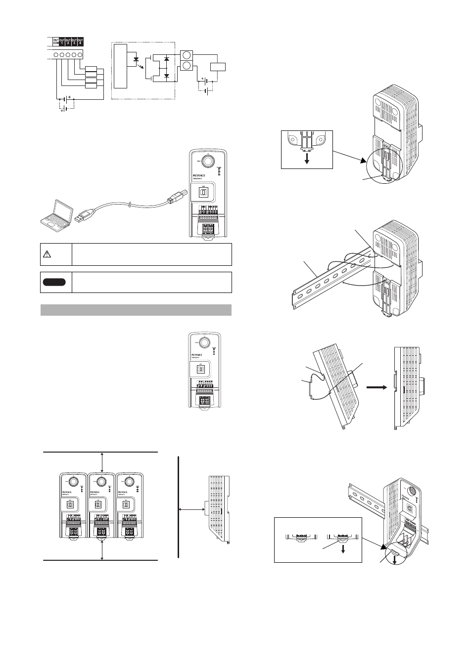
Wiring OUT1
to 4
■ Wiring the USB port
Connect the USB port of the N-UB to the USB port of the personal
computer. Connect the Type B connector of the USB cable to the N-UB
port.
■ Surrounding space
•
Install the N-UB vertically.
When the installation direction changes,
provide adequate surrounding space so
that heat does not build up.
•
For ventilation, maintain a space of 50mm
or more from the top and bottom of the N-
UB. As long as the N-UB is the only
source of heat generation, the N-UB can
be installed without space on the right
and left sides.
Provide a space of 80 mm or more in front
of the N-UB to connect the BL head.
50 mm or more on the top and bottom; no space is required on the
right and left sides
■ Installation precautions
•
When installing the N-UB, do not block the ventilation slots on the
top and bottom of the unit. Otherwise, heat builds up inside the
unit, causing product failure.
•
If the temperature on the N-UB will foreseeable exceed the upper
limit of the operating temperature (50
°C), take appropriate
measures such as performing forced air cooling or ensuring
proper ventilation so that the temperature does not exceed the
upper limit of the normal operating temperature (50
°C).
■ Installing and removing the N-UB to and from the DIN
rail
•
Installing the N-UB to the DIN rail
1
Lower the mounting tab on the back of the N-UB.
Check that the mounting tab is placed in the position shown in the
following diagram.
2
Install the N-UB to the DIN rail as shown in the following
diagram.
•
Removing the N-UB from the DIN rail
1
Lower the mounting tab as shown in B in the following
diagram, and then remove the N-UB.
2
After the N-UB is removed, return the mounting tab to the
state shown in A.
CAUTION
The length of the USB cable must be 5 m or less.
Note
Users must install the USB Driver to communicate with
the N-UB through a PC.
Installing the N-UB
OUT1 to 4
OUT
COM
Load
Circuit diagram
Load
Load
Load
Load
In
ter
nal
ci
rcui
t
To the USB port of the
personal computer
USB cable
Top
Bottom
80 mm or more
from the front
80 mm
50 mm
50 mm
Mounting tab
DIN rail
Protrusion
DIN rail
Protrusion
Mounting tab
1. Hook
2. Push
Installing the N-UB to the DIN rail
Mounting tab
Lower with a screw
driver or another tool.
A
B