Wiring the rs-422a/485 connector, Processing the communication cable, Installing the n-r4 – KEYENCE N-R4 User Manual
Page 3: Surrounding space, Installation precautions
3
E N-R4-IM
•
Wiring IN1 and IN2
•
Wiring OUT1
to 4
■ Wiring the RS-422A/485 connector
•
Layout of RS-422A pins
•
Wiring the RS-422A
Use a twisted pair cable
•
Layout of RS-485 pins
•
Wiring the RS-485 (wiring to the N-410)
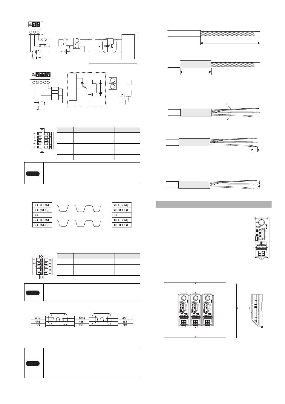
■ Processing the communication cable
1
Remove the sheath of the cable by 70 mm.
2
Cover the bare shield mesh wires and the sheath portion
with a contraction tube of about 40 mm.
3
Make stranded wires from the shield mesh wires and
prepare the required number of wires including the insulated
wires. (5 wires are required for the RS-422A and 3 wires are
required for the RS-485)
4
Remove the cover of each insulated wire by about 8 mm
from the tip.
5
Perform preliminary soldering on each wire by about 6 mm
from the tip.
The external diameter of the preliminarily soldered bare wire
must not exceed 2 mm.
■ Surrounding space
•
Install the N-R4 vertically.
When the installation direction changes, provide
adequate surrounding space so that heat does not
build up.
•
For ventilation, maintain a space of 50mm or more
from the top and bottom of the N-R4. As long as the
N-R4 is the only source of heat generation, the N-R4
can be installed without space on the right and left
sides.
Provide a space of 80 mm or more in front of the N-
R4 to connect the BL head.
50 mm or more on the top and bottom; no space is required on the
right and left sides
■ Installation precautions
•
When installing the N-R4, do not block the ventilation slots on the
top and bottom of the unit. Otherwise, heat builds up inside the
unit, causing product failure.
•
If the temperature of the N-R4 will foreseeable exceed the upper
limit of the operating temperature (50
°C), take the appropriate
measures such as performing forced air cooling or ensuring
proper ventilation so that the temperature does not exceed the
upper limit of the normal operating temperature (50
°C).
Symbol
Description
Signal direction
SD+
Data transmission + side
Output
SD–
Data transmission – side
Output
SG
Signal ground
-
RD+
Data reception + side
Input
RD–
Data reception – side
Input
Note
• The extended distance of the cable must not exceed
1.2 km.
• For both the N-R4 and external equipment, set the
terminating resistance to ON.
(The terminating resistance of the N-R4 is 100
Ω.)
Symbol
Description
Signal direction
485+
RS-485 + side
I/O
485–
RS-485 – side
I/O
SG
Signal ground
-
Note
• The extended distance of the cable must not exceed
1.2 km.
• For the N-R4 at the end of the RS-485 trunk line, set
the terminating resistance to ON.
Note
• Do not wire the RS-485 cable via the terminal block.
• Do not install the RS-485 cable and the power line on
the same piping.
• Do not branch the RS-485 line.
• Use stranded copper wire having a gage of AWG12 to
30 and temperature rating of 60
°C or higher.
• The tightening torque is 0.56 to 0.79 N·m (5 to 7 lbf·in).
Circuit diagram
IN1, IN2
INCOM
Internal
circuit
OUT1 to 4
OUT
COM
Load
Circuit diagram
Load
Load
Load
Load
In
te
rn
al
ci
rc
ui
t
External equipment
N-R4
Recommended RS-422A cable (with shield)
Manufacturer: NIHON ELECTRIC WIRE & CABLE Co., LTD
Product name:Instrumentation cable
Model:
KNPEV-SB 0.75 mm
2
x 2P
N-R4
Recommended RS-485 cable (with shield)
Manufacturer: NIHON ELECTRIC WIRE & CABLE Co., LTD
Product name:Instrumentation cable
Model:
KNPEV-SB (1P) 0.75 mm
2
N-R4
N-R4
Installing the N-R4
Sheath
About 70 mm
Contraction tube
About 40 mm
Shield stranded wire
Insulated wire
About 8 mm
2 mm or less
Top
Bottom
80 mm or more
from the front
80 mm
50 mm
50 mm