Part names and functions, System configuration figure, When connecting rs-422a or rs-485 (1:1 connection) – KEYENCE N-R4 User Manual
Page 2: Rs-485 connection (multi-drop connection), Connection and wiring methods, Connecting the code reader, Connecting the power supply, Layout and wiring of the i/o terminal block, Kv -b 16x c
2
E N-R4-IM
•
States of RS-422A/485 changeover switch and terminating
resistance switch
* The factory setting is RS-485 communication mode and terminating
resistance OFF.
■ When connecting RS-422A or RS-485 (1:1 connection)
■ RS-485 connection (multi-drop connection)
* At the end of the RS-485 trunk line, set the terminator to ON.
■ Connecting the code reader
Connect the code reader to the head port of the N-R4.
Pin layout of the head port
■ Connecting the power supply
Connect the 24 VDC power supply to the power terminal of the N-R4.
The dimensions of crimp contacts used for wiring should be as follows:
■ Layout and Wiring of the I/O Terminal Block
•
Layout of the I/O terminal block
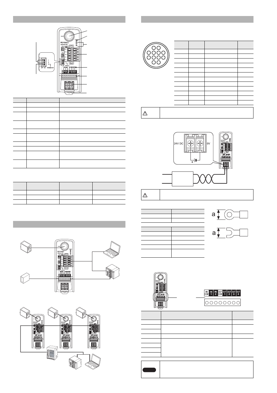
Part Names and Functions
Number
Name
Function
1
Head port
Used to connect the head.
2
Power LED
Lights when the power is ON.
3
Communication status
LED
Monitors the status of communication with the
head.
4
RS-422A/485
connector
Used to connect to the host (personal
computer, PLC).
5
I/O status LED
Monitors the ON/OFF status of I/O terminals.
6
I/O terminals
Used to connect I/O signal lines of control
units.
7
Power terminal
Terminal for 24V DC power supply input.
8
DIN rail mounting tab
A tab for mounting the DIN rail.
9
RS-422A/485
changeover switch
Used to switch between RS-422A and 485
communications.
10
Terminating resistance
switch
Used to switch between ON and OFF of the
terminating resistance.
Number
RS-422A
communication mode
RS-485
communication mode
Terminating
resistance ON
1
Left
Right
-
2
Left
Right
-
3
-
-
Right
System Configuration Figure
8. DIN rail mounting tab
1. Head port
2. Power LED
3. Communication
status LED
4. RS-422A/485
connector
5. I/O status LED
6. I/O terminals
7. Power terminal
9. RS-422A/485
changeover switch
10. Terminating
resistance switch
KV
-B
16X
C
Head port
OUT1 to 4
IN1
Head
BL Series
SR Series
Personal
computer
Timing sensor
RS-422A
or RS-485
RS-232C
RS-485
Personal
computer
PLC
RS-485 master unit
N-410
Head (BL Series, SR Series)
Connection and Wiring Methods
Pin
number
Name
Signal name
Signal
direction
1
OUT1
OUT1 input
Input
2
OUT2
OUT2 input
Input
3
RXD
RS-232C Receive
Input
4
RTS
RS-232C Receivable
Output
5
OUT4
OUT4 input
Input
6
IN2
IN2 output
Output
7
TXD
RS-232C Transmit
Output
8
CTS
RS-232C Transmittable
Input
9
OUT3
OUT3 input
Input
10
IN1
IN1 output
Output
11
+5V
+5V power supply
Output
12
GND(SG)
Common GND
-
CAUTION
Install and remove connection cables with the power
disconnected.
CAUTION
Using a power supply other than 24 VDC may cause
product failure.
Terminal
Dimensions
Round Terminal
a: 6 mm Max.
Y terminal
a: 6 mm Max.
Item
Description
Wire size
AWG14-22
Tightening torque
0.49 N·m (4.34 lbf·in)
Wire material
Copper
Wire type
Stranded wire
Electric wire
temperature rating
+60
°C max.
Symbol
Description
Signal
direction
INCOM
Common for IN terminal
-
IN1
Used as an input terminal for the code reader.
Input
IN2
OUTCOM
Common for OUT terminal
-
OUT1
Used as an output terminal from the code reader.
Output
OUT2
OUT3
OUT4
Note
• For connection, use stranded copper wire having a
gage of AWG16 to 26 and temperature rating of 60
°C
or higher.
• The tightening torque is 0.19 N·m (1.7 lbf·in).
3
7
4
8
5
1
2
9
11
12
6
10
Round 12-pin jack
Power supply
24V+10%
-20%
Twist pair cable
I/O terminal
block