Precautions for installation, 2 connection and installation, Installing the sj-m series – KEYENCE SJ-M300 User Manual
Page 6: Connection and installation, Freq
5
2-1
Before Installation
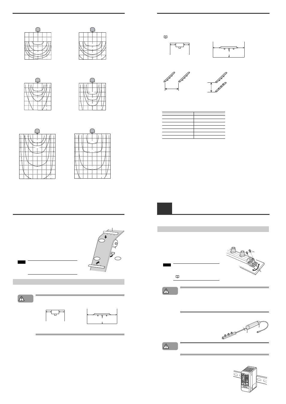
Model: SJ-M030V/030VC
At the time of frequency 50 Hz
Model: SJ-M070V/070VC
At the time of frequency 50 Hz
Measurement conditions:
The time required to eliminate the static charge of the
target from ±3000 V to ±300 V is measured.
The downward air flow: 0 m/sec
The air purge:
1 NL/min (1 electrode)
Measurement conditions:
The time required to eliminate the static charge of the
target from ±3000 V to ±300 V is measured.
The downward air flow: 0 m/sec
The air purge:
1 NL/min (1 electrode)
At the time of frequency 8 Hz
At the time of frequency 8 Hz
Measurement conditions:
The time required to eliminate the static charge of the
target from ±5000 V to ±500 V is measured.
The downward air flow: 0.3 m/sec
The air purge:
1 NL/min (1 electrode)
Measurement conditions:
The time required to eliminate the static charge of the
target from ±5000 V to ±500 V is measured.
The downward air flow: 0.3 m/sec
The air purge:
1 NL/min (1 electrode)
At the time of frequency 1 Hz
At the time of frequency 1 Hz
Measurement conditions:
The time required to eliminate the static charge of the
target from ±5000 V to ±500 V is measured.
The downward air flow: 0.3 m/sec
The air purge:
1 NL/min (1 electrode)
Measurement conditions:
The time required to eliminate the static charge of the
target from ±5000 V to ±500 V is measured.
The downward air flow: 0.3 m/sec
The air purge:
1 NL/min (1 electrode)
50
100
150
50
100
150mm
50
100 150mm
0.4sec
0.6sec
1.0sec
1.5sec
2.0sec
50
100
150
50
100
150mm
50
100 150mm
0.4sec
0.6sec
1.0sec
1.5sec
2.0sec
150
300
450
300
600
900mm
150 300 450mm
10sec
15sec
30sec
5sec
150
300
450
300
600
900mm
150 300 450mm
10sec
15sec
30sec
5sec
300
450
600
150
450
300
150
600mm
300
600
900
1200
1500mm
20sec
30sec
10sec
6sec
4sec
300
450
600
150
450
300
150
600mm
300
600
900
1200
1500mm
20sec
30sec
10sec
4sec
2-1
Before Installation
■ Proper static elimination
To ensure proper static elimination, consider the following points.
If the target is in contact with metallic objects (grounding
conductor), the static charge of the target is not completely
eliminated.
Install the SJ-M Series in a location in which the target is not in
contact with any metallic objects (such as a grounding conductor).
If the film or sheet is an electrical insulator, only the static
electricity on the surface exposed to the static elimination bar
is eliminated.
To eliminate the static electricity on both surfaces, use another
SJ-M unit on the other side.
Precautions for installation
■ Locations
Refer to the following illustration to install the SJ-M Series.
• Provide enough space between the static elimination bar and surrounding
walls as shown in the figures below.
• When mounting the SJ-M Series, use the provided mounting bracket,
otherwise an accident or malfunction may result.
Target (film or sheet)
Metal roller
NG
OK
OK
• Install the static elimination bar in a
location that allow easy maintenance
access (to replace or clean parts).
Note
CAUTION
20mm
min.
20mm
min.
20mm min.
30mm
min.
30mm
min.
2-1
Before Installation
■ Interference
The Static Elimination Head may not function properly if there is a conductor (earthed body) located
nearby or if two or more units are used close to each other. In such an installation, refer to the figure
below and maintain the indicated distance between the conductor (earthed body). If a conductor (earthed
body) is located inside the distances indicated below, adjust using the ion balance manual setup.
"Ion Balance Adjustment Function" (page 7)
If two SJ-R units are used, refer to the following illustration and separate the static elimination bars
properly.
The interference distance between the conductive object and the static elimination bar and that
between the static elimination bars located in parallel are specified, on condition that the target is
located at the following distances under a down flow of 0.3 m/s.
The interference distance between the static elimination bars located face to face is specified under no
wind flow.
Frequency (Hz)
Operating distance (mm)
50
50
30
150
10
300
8
600
5
900
3
1200
1
1500
20mm
min.
20mm
min.
20mm min.
30mm
min.
30mm
min.
Side-to-side installation
300mm
min.
Face-to-face installation
100mm
min.
2-2
Connection and Installation
This section describes how to connect and install the Static Elimination Head and Controller Unit.
Installing the SJ-M Series
■ Installing the Static Elimination Bar
●
Install the static elimination bar in the desired location.
Adjust the angle of the mounting brackets so that the
static elimination bar is properly secured at the desired
angle. Tap M4 screw holes at the appropriate location
and secure the static elimination bar using M4 screws.
• Do not allow any objects to contact the static elimination bar after
installation, as this may lead to product breakdown.
• When installing the SJ-M Series, observe the minimum bending radius of all
provided cables. Also, do not install the SJ-M Series with the cables
deformed by staples or other objects. Doing so might cause the SJ-M Series
to malfunction.
●
When the mounting fixture is used:
When installing the drive unit, prepare tapped
mounting holes, and install the drive unit at a tightening
torque of 1 Nm or less (M4 screws: 1 Nm or less).
The M3 screws and bundling band for fastening the
mounting fixture must be prepared separately.
Make a space of 30 mm or more around the drive unit. Otherwise, the unit may
be damaged.
■ Installing the Controller unit
Mount the Controller Unit on the DIN rail.
M4 screws
M4 taps
In case of the side mounting, use the
ion balance adjustment function to
adjust the ion balance again.
(
page 7)
Note
CAUTION
M4 Tap
CAUTION
FREQ