2 checking the contents of the package, Package contents, Options – KEYENCE SJ-M300 User Manual
Page 4: 3 names and functions of parts, Static elimination bar, Controller unit (operation/display section), Controller unit (i/o terminal section), Checking the contents of the package, Names and functions of parts, Freq
3
1-2
Checking the Contents of the Package
The package contains the following components and accessories. Before you start using the SJ-M
Series, make sure that the package contains everything that it is supposed to contain. A Replacement
Electrode Unit and other accessories are available as options.
"Appendices - List of Options" (page 13)
Package Contents
Options
WARNING labels (Japanese, German, French, Italian and Chinese
(Simplified)) *
* Use as necessary.
Compact Spot-type Static Eliminator
Instruction Manual
SJ-M Series
Before using this Compact Static Eliminator, be sure to
thoroughly read this Instruction Manual.
After you are finished with this Instruction Manual, be
sure to store it in a safe place for quick reference.
Compact Spot-type Static Eliminator
Instruction Manual
SJ-M
96M1533
Controller Unit (SJ-M300)
Static Elimination Bar
Instruction Manual
SJ-M030/070 Series
Mounting Fixture
1set
Flat-blade
screwdriver
Earth lead
AC Adapter SJ-U2
Extension cable SJ-C3
(3m cable, can be extended to 9m)
Tungsten electrode probe for SJ-M030/070 (set of 4 pieces) OP-42213
Silicon electrode probe for SJ-M030/070C (set of 4 pieces)
OP-42214
Tungsten electrode probe for SJ-M030/070G (set of 4 pieces) OP-51644
Tungsten electrode probe for SJ-M030/070V (set of 4 pieces) OP-75352
Silicon electrode probe for SJ-M030/070VC (set of 4 pieces) OP-75353
* For details of the AC cable, contact the
KEYENCE sales office in your district.
1-3
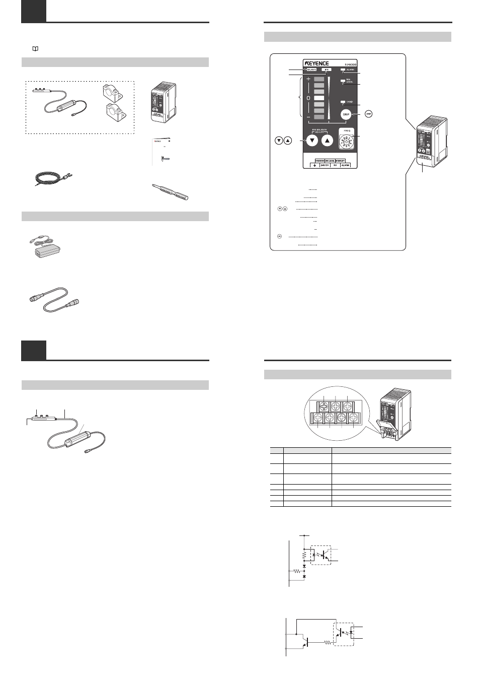
Names and Functions of Parts
This section describes the names and functions of parts on the SJ-M Series.
Static Elimination Bar
●
SJ-M030/070 Series
(2)
(3)
(4)
(1)
(1) Electrode probe
Ion charge is emitted from the tip of this probe.
(2) Air duct
Supplies clean dry air.
(3) High-voltage cable
Ambient operating temperature: 0 to +40°C
Minimum bending radius 30 mm
(4) Drive unit
Manages body information of the Static
Elimination Bar or drives the Bar.
1-3
Names and Functions of Parts
Controller Unit (operation/display section)
Enlarged view of display section
Terminal plate cover
Lights when the charged level of the target object is
displayed.
Lights when the ion emission level is being displayed.
Indicates the charged level of the target object.
Also, indicates the ion emission level.
Used for adjusting the ion balance and for selecting setting
items.
Lights when an alarm occurs.
Lights when the ion emission level has fallen below the set
value due to dirt or wear of the electrode probe.
Lights when the charged level of the target object is high
and static cannot be completely eliminated.
Used for determining setting items and for switching the
display.
Used for switching the frequency.
Ion balance
indicator
Ion level
indicator
Ion monitor
keys
key
Alarm indicator
Ion level alarm indicator
Condition alarm indicator
Ion balance indicator
Ion level indicator
Ion monitor
keys
Alarm indicator
Ion level alarm indicator
Condition alarm indicator
key
Rotary switch
(1)
(2)
(3)
(4)
(5)
(6)
(7)
(8)
(1)
(2)
(3)
(4)
(5)
(6)
(7)
(8)
(9)
(9) Rotary switch
FREQ
1-3
Names and Functions of Parts
Controller Unit (I/O terminal section)
■ Input circuit diagram
■ Output circuit diagram
Number
Name
Function
(1)
Condition alarm output
terminal
Outputs when static elimination performance is influenced by excessive
charge.
(2)
Ion level alarm output
terminal
Outputs when the ion emission level drops.
(3)
Static elimination stop input
terminal
Static elimination can be turned ON/OFF by shorting this terminal with
(6).
(4)
Ground terminal
Be sure to connect a Class D earth (maximum resistance of 100 Ohms).
(5)
DC power terminal
24 VDC ±10%
(6)
0V terminal
0V for power and 0V for I/O
(7)
Alarm output terminal
Outputs when an alarm occurs.
(1)
(4)
(5)
(6)
(7)
(2)
(3)
+24V
3k
Ω
INPUT( (3) )
0V( (6) )
Input a no-voltage contact (relay, etc.)
or NPN open collector to INPUT and 0V.
[ (3) (static elimination stop input)]
OUT
DC40V
100mA
0V( (6) )
Open collector output
[ (2) (ion level alarm output), (1) (condition alarm output), (7) (alarm output)]