Sensor configuration – KEYENCE AP-C40W(P) Series User Manual
Page 3
3
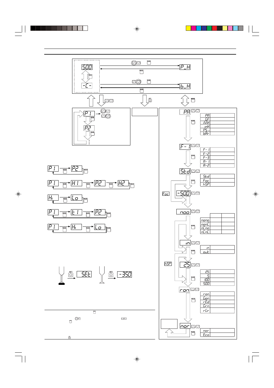
Detection mode
Operating mode
Standard
Focus mode
High-speed
Zero shift input
Analog output
N.O./N.C.
2.5
msec
5
msec
100
msec
500
msec
General-purpose mode
Variable hysteresis mode
Window mode
Application mode 1
Application mode 2
Analog/zero shift
Standard
Eco mode
Power-save
Chatter prevention
Sets response time.
* F-1 and F-2 mode only
Values that fall between the P1 and P2
settings will be displayed in green,
while values outside that range will be
displayed in red.
When
A-1/A-2 is
selected
during
fixed mode
operation
When
operating
mode is
• Two-point tuning
• Active tuning
* High-speed mode provides a 1-ms
high-speed response.
*1 Displayed in kPa during focus mode operation.
*2 Displayed in gf/cm
2
during folus mode operation.
*3 Displayed in bar during standard mode operation.
Displayed in mbar during focus mode operation.
Current value
Reference value
Hold value
Units
Increase the
setting.
Decrease the
setting.
For other
than
Focus center pressure
After 4 sec
of no key
operation.
Reference value*
Press for 3 sec or more.
+
+
■
Toggling the
display
■
Manual configuration
Settings are
manually
configured. The
display changes
for each mode.
* Toggling the
display of
settings (see the
diagram below).
* Manual configuration
only during F-3/A-2
mode operation.
Current value
Peak hold
Bottom hold
* The reference value is
the pressure value when
zero shift input is
received and is replaced
only when zero shift
input is selected.
■
Mode
configuration
* See the Focus Mode section
of Part 10 for the center
pressures that can be
selected.
N.O.
N.O.
N.C.
N.C.
N.O.
N.C.
N.C.
N.O.
Control
output 1
Control
output 2
• N.O.
= normal open.
• N.C.
= normal close.
Display color (7-segment)
ON: Red, OFF: Green
ON: Green, OFF: Red
Normally red
Normally green
Within set value: Green
Outside set value: Red
(
)
kPa (41, 43, 44, 48),MPa (43)*
1
kgf/cm
2
(43)kgf/cm
2
*
2
(48)
mmHg (41, 44)
inHg (41, 44)
psi (41, 43, 44, 48)
mbar (41, 44, 48)*
3
, bar (43)
9. Sensor Configuration
■
Toggling the display of settings
●
General-purpose mode/F1
●
Variable hysteresis mode/F-2
●
Window mode/F-3
●
Application mode 1/A-1
●
Application mode 2/A-2
■
Two-point tuning (F-1/F-2)
The sensor is made to detect the pressures when the target object is
present and then absent for confirmation of target suction pick-up, and
the intermediate value is used.
Control output 1 configuration: When P1 (H1) is selected on the settings
display.
Control output 2 configuration: When P2 (H2) is selected on the settings
display.
Flashes
for 3 sec.
Setting
Target object
present
Target object
absent
■
Active tuning (A-1)
See Section 11.
Note:• Press and hold the MODE button (
) for at least 3 seconds to return to the current
value/reference value/hold value display from each of the mode setting screens.
• Press the left side
on the manual adjustment button (
) while holding down the
mode button (
) to return to the previous display.
• The current value will be displayed based on the ambient pressure conditions prevalent
at that time without regard to zero shift input when the P2 setting display is selected for
A-1 mode or when the HI and Lo setting displays are selected for A-2 mode.
• The sensor must be configured manually when operating in the F-3/A-2 modes. The
SET button (
) will not function.