KEYENCE DL-RS1A User Manual
Page 14
12
Parameters of Commands and Responses
*3
This data type can only be read when the Detection mode of the sensor amplifiers is "Peak-to-peak" hold.
This data type allows you to read the peak and bottom values during the measurement period.
*4
This data type can only be read when the calculation function is used.
The data can only be read from the main unit (ID: 00) when performing a calculation other than
reference difference. DL-RS1A reads the R.V. values of the expansion units (ID: 01 - 14), which
are used in the calculation, from the main unit. (Only the main unit holds the R.V. values.)
When performing reference difference, the data can only be read from the expansion units. (Only
the expansion units hold the R.V. values.) DL-RS1A reads the R.V. value of the main unit and the
expansion units, which are used in the calculation, from the expansion units.
When using the calculation function, the sensor amplifiers can only hold the P.V. values
of the calculation results.
By using these read commands, the R.V. values of the sensor amplifiers on which the
held calculation result was based can be read. Therefore, it is possible to read the R.V.
value of each sensor amplifier without being affected by the response delay.
*5
When the data read from the sensor amplifiers is one of the following values, it is not a
comparator value but has a specific meaning.
*6
You can read data number "006" to check the error status of the sensor amplifiers.
Convert the five digit number (ASCII characters) read from the sensor amplifiers to a binary
number and check the ON/OFF state of each bit to check the error.
For information on each error, refer to "GT2 Series User's Manual".
•
When the data read from a sensor amplifier is "00033":
"33" converted to binary number is "0000 0000 0010 0001".
Therefore, this data indicates that a "number of units error" and an "overcurrent error"
have occurred at the sensor amplifier from which it was read.
•
If no error has occurred at the sensor amplifier, the data "00000" is returned.
Reference
Data read from
sensor amplifier
Description
+EEE.EEEE
The sensor amplifier is in an error state.
+999.9999
The value exceeds the upper limit of the detection range.
-999.9999
The value is below the lower limit of the detection range.
-999.9998
·
In cases such as when using the hold mode, the display
of the P.V. value of the sensor amplifier shows "------".
·
When using the GT2-100 Series, the data of the ID out of
the range of the valid ID setting is read.
Bit
Sensor amplifier errors
0
Overcurrent error (ErC)
1
Head error (ErH)
2
EEPROM error (ErE)
3
Core alarm error (Er.chK)
4
Self-timing delay error (Er.dLY)
5
Number of units error (Er.Unit)
6
Calculation error (Er.CAL)
7
Calculation only mode error (Er.noH)
8 to 15
Not used
Reference
Reference
Bit 5: Number of units error
Bit 0: Overcurrent error
Parameters of Commands and Responses
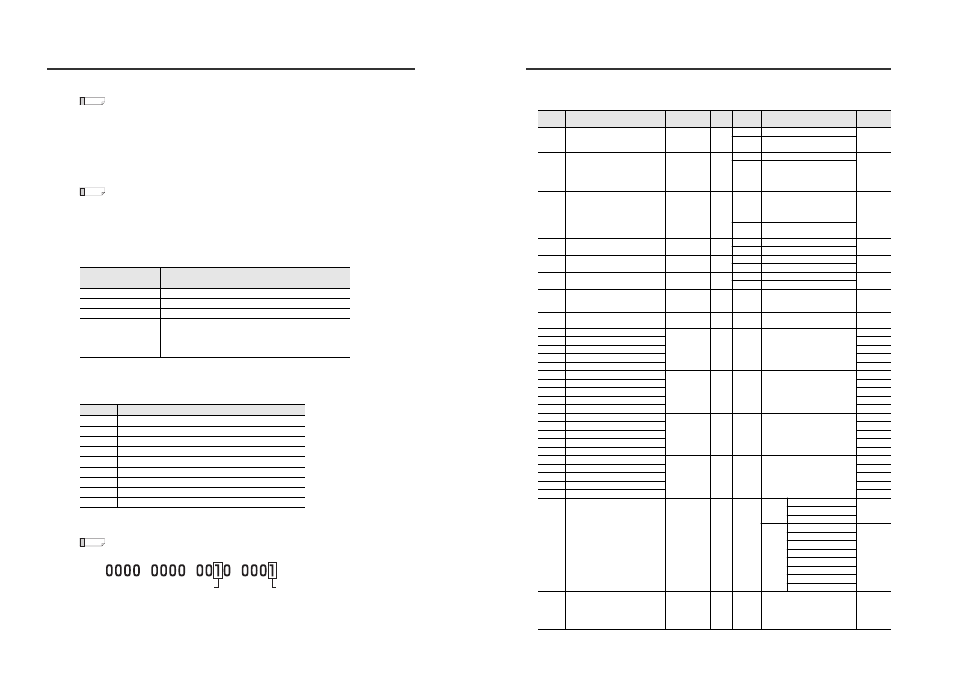
z Read/write data
The following table lists the types of data that can be read from and written to GT2 Series sensor amplifiers.
Data
number
Data name
Data format
*1
Number
of bytes
Attribute
*2
Data range
Initial
value
050
Perform preset request
*
1
R
0 - 2: Last written value
1
W
0
o 1: Perform preset
*3
0
o 2: Perform preset reset
*3
051
Bank switching state
*
1
R
0 - 3: Current active bank
0
W
*4
0: Switch to bank 0
1: Switch to bank 1
2: Switch to bank 2
3: Switch to bank 3
052
Timing status
*
1
R
0: Timing input OFF or measuring
with self-timing
1: Timing input ON or not
measuring with self-timing
0
W
0: Switch while measuring
1: Switch while not measuring
053
Reset request
*
1
R
0 - 1: Last written value
1
W
0
o 1: Perform reset
*3
054
Initial reset request
*
1
R
0 - 1: Last written value
1
W
0
o 1: Perform initial reset
*3
055
Error clear request
*
1
R
0 - 1: Last written value
1
W
0
o 1: Perform error clear
*3
056
Keylock
*
1
R/W
*5
0: Unlock
1: Full key lock
2: Key lock
0
057
Bar display mode
*
1
R/W
*6
0: Bar display mode
1: OK/NG display mode
0
060
Bank 0 HH setting
*7
±***.****
9
R/W
-199.9999 to +199.9999
+007.0000
061
Bank 0 HIGH setting
+005.0000
062
Bank 0 LOW setting
+001.0000
063
Bank 0 LL setting
*7
-001.0000
064
Bank 0 preset value
+000.0000
065
Bank 1 HH setting
*7
±***.****
9
R/W
-199.9999 to +199.9999
+007.0000
066
Bank 1 HIGH setting
+005.0000
067
Bank 1 LOW setting
+001.0000
068
Bank 1 LL setting
*7
-001.0000
069
Bank 1 preset value
+000.0000
070
Bank 2 HH setting
*7
±***.****
9
R/W
-199.9999 to +199.9999
+007.0000
071
Bank 2 HIGH setting
+005.0000
072
Bank 2 LOW setting
+001.0000
073
Bank 2 LL setting
*7
-001.0000
074
Bank 2 preset value
+000.0000
075
Bank 3 HH setting
*7
±***.****
9
R/W
-199.9999 to +199.9999
+007.0000
076
Bank 3 HIGH setting
+005.0000
077
Bank 3 LOW setting
+001.0000
078
Bank 3 LL setting
*7
-001.0000
079
Bank 3 preset value
+000.0000
100
Calculation mode
*8*9
Calculation setting
**
2
R/W
Higher digit
0: Do not use calculation function
0
1: Use calculation function
2: Calculation dedicated mode
Lower
digit
0: Maximum value
0
1: Minimum value
2: Degree of flatness
3: Average
4: Reference difference
5: Twist
6: Warpage
7: Thickness
101
Detection mode
*
1
R/W
0: Standard
1: NG hold
2: Peak hold
3: Bottom hold
4: Peak-to-peak
0