Names of each part, Installation and connection to sensor amplifiers, Mounting on a din rail – KEYENCE DL-DN1 User Manual
Page 2: How to connect to the sensor amplifier
2
Names of Each Part
Installation and Connection to Sensor Amplifiers
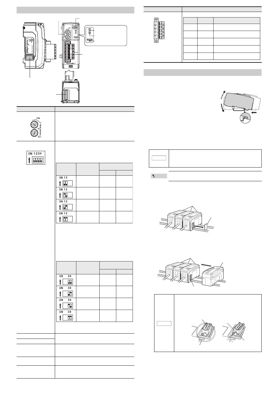
Mounting on a DIN rail
1
Fit the tab of the lower part of the main unit to the
DIN rail. While inserting the main unit in the
direction of arrow 1, push the body in the direction
of arrow 2.
2
To detach the main unit, while pushing the
main unit in the direction of arrow 1, pull the
body in the direction of arrow 3.
How to connect to the sensor amplifier
The DeviceNet Compatible Network Unit DL-DN1 is used by connecting it to a sensor
amplifier. The connection method varies according to the mounting type of the sensor
amplifier to connect to.
z
Connecting to a DIN rail mounting type sensor amplifier.
1
Detach the expansion protective cover of the sensor amplifier to which the
communication unit is to be connected.
2
Mount the DeviceNet Compatible Network Unit DL-DN1 on the DIN rail and
connect to the sensor amplifier.
Push and fix the DeviceNet Compatible Network Unit DL-DN1 to make sure there is no
space between the output unit and the sensor amplifier.
Item
Description
(1) Address setting switch
Sets the DeviceNet node address of the DL-DN1.
x10 : Ten's digit
x1 : One's digit
Setting range : 00 to 63
Default value : 63
When setting the node address of the DL-DN1 from the
DeviceNet master unit, set it in the range of 64 to 99.
The DL-DN1 turns into the PGM.
(2) Operating mode setting
switch
Sets the operating mode of the DL-DN1 in the DeviceNet.
The data that can be handled in I/O communication varies
with each operating mode.
Basic mode
Use switch bits 1 and 2 to configure the basic mode.
Default value : 3-output mode
• The content of output depends on the sensor amplifiers to
be connected.
Examples: 3-level judgment output for 3-output mode;
5-level judgment output for 5-output mode
• The size of occupied memory depends on the number of
amplifiers to be connected.
Extended mode
Switch bits 3 and 4 can be set to add one of the following
extended functions to the basic mode.
Default value : No extended mode
The size of occupied memory depends on the number of
amplifiers to be connected and the setting of the basic mode.
(3) Module status indicator
When normal: Lit in green
(4) Network status indicator
(5) Sensor communication
indicator
Indicates the status of communication between the DL-DN1
and sensor amplifiers.
When normal: Lit in green
(6) Sensor amplifier connector
(for DIN rail mounting)
Attach the sensor amplifier to this connector.
(7) Sensor amplifier
connector (for panel
mounting/large display)
Attach the sensor amplifier to this connector.
When shipped from the factory, a protection sticker is installed.
The optional extended cable (OP-35361) is used for this connection.
(4) Network status indicator
(green/red)
(1) Address setting switch
(6) Sensor amplifier connector
(for DIN rail mounting)
(7) Sensor amplifier connector
(for panel mounting /
large display)
(8) DeviceNet connector
(5) Sensor communication
indicator (green/red)
(3) Module status indicator
(green/red)
(2) Operating mode setting switch
DL
-DN
1
20-30V DC, Class2
15JN
IND.CONT.EQ.
Switch setting Operating mode
3-output mode
5-output mode
"3-output +
current value" mode
"5-output +
current value" mode
Occupied memory
(No extended mode)
IN area
OUT area
8 byte
12 byte
14 to 70 byte
18 to 74 byte
0 byte
0 byte
0 byte
0 byte
Switch setting Operating mode
No extended mode
External input mode
"External input +
bank switching"
mode
"External input +
setting value change"
mode
IN area
OUT area
-
14 to 84 byte
18 to 88 byte
22 to 96 byte
-
6 to 10 byte
10 to 14 byte
24 to 40 byte
Occupied memory
(Including basic mode)
(8) DeviceNet connector
Attach the DeviceNet cable to this connector.
When connecting the DeviceNet Compatible Network Unit DL-DN1,
be sure to check the power of sensor amplifier is OFF before
performing the operation. Performing the operation when the
power of sensor amplifier is ON may damage the equipment.
Refer to the Instruction Manual of each sensor amplifier for
details about how to add the sensor amplifier.
Refer to the figure below, and check that the sensor amplifier
connector (for DIN rail mounting type) on the side of the
DeviceNet Compatible Network Unit DL-DN1 is not mounted at
an angle. Connecting to the sensor amplifier with the
connector diagonally may damage the equipment.
Item
Description
Black
Blue
White
Red
Wire color Signal name
Function
V-
V+
Connects 0 volt of the communication
power supply.
Blue
Black
CAN_L
Communication signal (Low)
Bare wire
SHIELD
Connects the shield of the
DeviceNet cable.
White
CAN_H
Communication signal (High)
Red
Connects 24 VDC of the communication
power supply.
(1)
(2)
(3)
NOTICE
Point
Sensor amplifier
Expansion protective cover
Sensor amplifier
DeviceNet Compatible
Network Unit DL-DN1
Connector
NOTICE
Sensor amplifier connector
DeviceNet Compatible Network Unit DL-DN1