Making sensitivity settings, Fine-adjusting sensitivity, Percentage (%) calibration – KEYENCE FS-32C(P) User Manual
Page 2: Output selection, Dynamic sensitivity correction (dsc) function, Edge detection mode
2
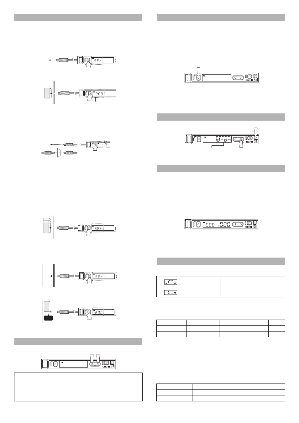
Making Sensitivity Settings
Two-point Calibration
In this mode, the PV used will be the mean value of two sensing values obtained
with and without a workpiece.
1
Press the SET button without any workpiece placed in front of the fiber unit.
2
Place a workpiece placed in front of the fiber unit, and press the SET button.
If the sensitivity difference does not have enough room, “” flashes for about two seconds
after the calibration is complete. The set value is stored in memory even in that case.
Maximum Sensitivity Setting
Set the sensitivity without a workpiece in the case of the reflective type, and with a
workpiece in the case of the through-beam or retro-reflective type.
Press the SET button for three seconds in the state as shown in the above figure.
(Release the button when SET flashes.)
When setting the sensitivity, set the value slightly higher than the received light intensity.
Full Auto Calibration
In this mode, the PV will be set to the mean value of the maximum and minimum incident
values obtained within a certain period. Use this mode to detect moving workpieces.
1
Press the set button for a minimum of three seconds while the target
workpiece is passing the sensing area of the fiber unit.
• While the SET button is pressed, the sensitivity of the sensor will be set
according to the incident values.
• After the setting is completed, the setting value is displayed on the digital monitor.
Positioning Calibration
1
Press the SET button without any workpiece placed in front of the fiber unit.
2
Place a workpiece on the position where you want to perform positioning.
Press the SET button for 3 seconds or longer until the display flashes.
Fine-adjusting Sensitivity
The setting value can be directly changed by pressing the manual button.
Percentage (%) Calibration
This is a calibration method that can set the setting value by percentage with ref-
erence to the received light intensity at the time of sensitivity setting.
For example, if the target value is set to –10P, the setting value is determined 10%
lower than the received light intensity when the SET button is pressed.
1
When selecting the sensitivity setting method (page 4, No. 2), select the %
calibration, and set the target value of calibration.
2
Taking the desired light intensity as a reference (normally without a
workpiece), press the SET button.
*
While the % calibration is in use, other calibrations (sensitivity setting) cannot
be used.
*
With FS-V31C(P)/32C(P), by periodically performing external calibration from
PLC or other devices, stable detection can be performed even with a small
sensitivity difference.
Output Selection
Either light-ON mode or dark-ON mode is selectable.
Dynamic Sensitivity Correction (DSC) Function
DSC automatically corrects the setting value according to the changes in the
received light intensity when there is no workpiece (output OFF).
This function is effective when the light intensity difference is small when judging
whether or not there is a workpiece.
At Detection mode selection (page 4, No.4), select “Dynamic sensitivity correction
mode” beforehand.*
How to set the sensitivity is the same as in the normal mode.
The DSC indicator illuminates when the DSC function is set.
*
When Light ON is selected, the upper limit of the correctable range is twice as
much as the initial setting value.
*
The value is stored in memory even after the power is turned off.
*
The DSC indicator flashes when the light intensity during output OFF greatly fluctuates
or the L/D ON selection is inappropriate. In such a case, check the setting again.
Edge Detection Mode
This mode detects the change in the received light intensity during a given period
of time.
Filter Setting
Basically, leave this setting as its initial value. If the passage interval of workpieces
is too short for the unit to respond, strengthen the level and try again.
The selectable filter level differs depending on the power modes.
*HSP: HIGH SPEED
As the number becomes smaller, the filter becomes stronger, which makes the unit difficult to
respond to gradual changes in light intensity.
Making Sensitivity Settings
The sensitivity is set to maximum when the SET button is pressed quickly once.
When the setting value is too low and the unit detects objects other than the work-
piece, fine-adjust the setting value to a higher number.
Operation When Switching Outputs
When extension display (page 5, No.8) is set for the number of digits to be
displayed for the received light intensity
1
Press the manual button quickly once, and check that the setting value flashes.
2
While the setting value is flashing, change the setting value with the Manual button.
DSC
DSC
When the setting is completed,
the setting value is displayed.
W
orkpiece
DSC
3 sec or longer
"Reflective model"
"Through-beam model"
DSC
W
orkpiece
DSC
W
orkpiece
DSC
When the setting is completed,
the setting value is displayed.
Head
W
orkpiece
SEL
M
DSC
Rising edge detection
Detects the increase (rising edge) of the
received light intensity
Falling edge detection
Detects the decrease (falling edge) of the
received light intensity
Filter level
HSP*
FINE
TURBO
SUPER
ULTRA
MEGA
Default state
5
8
9
9
9
9
Setting range
1 to 5
4 to 8
5 to 9
6 to 9
8 to 9
9 only
Setting
Operation
L-ON
Normally OFF. Turns ON only when the light intensity changes.
D-ON
Normally ON. Turns OFF only when the light intensity changes.
SEL
M
DSC
Press
Press (2) within five seconds
after pressing (1).
(1)
(2)
SEL
M
When the area detection mode is
selected, the selection options are
NO and NC.
DSC
SEL
M
DSC
DSC indicator