Hold function (hld), Shift function (sft), Clamp function(clp) – KEYENCE LR-ZB250AN/AP User Manual
Page 4: Troubleshooting, Warranties and disclaimers, Buyer's transfer obligations, Da* 2a, Qp q
4
LR-ZB250AN/P_IM_E
Hold function (Hd)
Display values can be held. The held value is updated each time the detected value
exceeds the setting value.
z
Setting procedure
1. Set the hold function (page 3).
2. Switch the display screen.
Shift function (F)
Turning the shift function ON will shift the display when tuning. In the Datum tuning/FGS,
the display value is shifted regardless of this function.
Clamp function(cP)
This can be used when the operation mode is set to “Distance (F-1)”. Turning the clamp
function ON will keep the previous display value and output status when light cannot be
received.
* The settings can be rewritten up to 1 million times when the operation mode is set to
“Distance (F-1)” and 10 thousand times in “I-DATUM mode (F-2)”.
(1) KEYENCE warrants the Products to be free of defects in materials and workmanship for
a period of one (1) year from the date of shipment. If any models or samples were
shown to Buyer, such models or samples were used merely to illustrate the general type
and quality of the Products and not to represent that the Products would necessarily
conform to said models or samples. Any Products found to be defective must be
shipped to KEYENCE with all shipping costs paid by Buyer or offered to KEYENCE for
inspection and examination. Upon examination by KEYENCE, KEYENCE, at its sole
option, will refund the purchase price of, or repair or replace at no charge any Products
found to be defective. This warranty does not apply to any defects resulting from any
action of Buyer, including but not limited to improper installation, improper interfacing,
improper repair, unauthorized modification, misapplication and mishandling, such as
exposure to excessive current, heat, coldness, moisture, vibration or outdoors air.
Components which wear are not warranted.
(2) KEYENCE is pleased to offer suggestions on the use of its various Products. They are
only suggestions, and it is Buyer's responsibility to ascertain the fitness of the
Products for Buyer’s intended use. KEYENCE will not be responsible for any damages
that may result from the use of the Products.
(3) The Products and any samples ("Products/Samples") supplied to Buyer are not to be
used internally in humans, for human transportation, as safety devices or fail-safe
systems, unless their written specifications state otherwise. Should any Products/
Samples be used in such a manner or misused in any way, KEYENCE assumes no
responsibility, and additionally Buyer will indemnify KEYENCE and hold KEYENCE
harmless from any liability or damage whatsoever arising out of any misuse of the
Products/Samples.
(4) OTHER THAN AS STATED HEREIN, THE PRODUCTS/SAMPLES ARE PROVIDED
WITH NO OTHER WARRANTIES WHATSOEVER. ALL EXPRESS, IMPLIED, AND
STATUTORY WARRANTIES, INCLUDING, WITHOUT LIMITATION, THE
WARRANTIES OF MERCHANTABILITY, FITNESS FOR A PARTICULAR PURPOSE,
AND NON-INFRINGEMENT OF PROPRIETARY RIGHTS, ARE EXPRESSLY
DISCLAIMED.
IN NO EVENT SHALL KEYENCE AND ITS AFFILIATED ENTITIES BE LIABLE TO
ANY PERSON OR ENTITY FOR ANY DIRECT, INDIRECT, INCIDENTAL, PUNITIVE,
SPECIAL OR CONSEQUENTIAL DAMAGES (INCLUDING, WITHOUT LIMITATION,
ANY DAMAGES RESULTING FROM LOSS OF USE, BUSINESS INTERRUPTION,
LOSS OF INFORMATION, LOSS OR INACCURACY OF DATA, LOSS OF PROFITS,
LOSS OF SAVINGS, THE COST OF PROCUREMENT OF SUBSTITUTED GOODS,
SERVICES OR TECHNOLOGIES, OR FOR ANY MATTER ARISING OUT OF OR IN
CONNECTION WITH THE USE OR INABILITY TO USE THE PRODUCTS, EVEN IF
KEYENCE OR ONE OF ITS AFFILIATED ENTITIES WAS ADVISED OF A POSSIBLE
THIRD PARTY’S CLAIM FOR DAMAGES OR ANY OTHER CLAIM AGAINST
BUYER. In some jurisdictions, some of the foregoing warranty disclaimers or damage
limitations may not apply.
BUYER'S TRANSFER OBLIGATIONS:
If the Products/Samples purchased by Buyer are to be resold or delivered to a third
party, Buyer must provide such third party with a copy of this document, all
specifications, manuals, catalogs, leaflets and written information provided to Buyer
pertaining to the Products/Samples.
E 1101-3
Power ON
Peak value
Detected value
Setting
value
2A*
Bottom value
Peak value
(Run Mode)
(
+
)
<1s
DA*
2A*
After calibration
(Example of a 2-point calibration)
Before calibration
Troubleshooting
Display
Description
Checks and Remedies
Control
Output
ErC
Current of 100 mA or more flows
through the control output
• Check power resistance.
• Check the control output cable for
contact with other cables.
OFF
Er
System error
Contact the nearest sales office.
OFF
Er
Laser diode failure
FAR
ErE
Error in the EEPROM that stores
sensor settings*
Normal
uuu
Excessive reflected light
Adjust the installation angle of the
sensor.
Inconsistent
___
Insufficient reflected light
• Verify that the detecting distance is
within specifications.
• Adjust the installation angle of the
sensor.
FAR
-FF
The detected object is too far
from the display range
• Move the target closer.
• Turn OFF the shift function.
Normal
i 0
to
i100
The operation mode is “I-DATUM
(F-2)”.
Use as is.
Normal
c
The key lock function is enabled
Release the key lock function by
pressing UP and DOWN at the same
time (> 3s).
Normal
P_H
The peak value is displayed
Press UP and DOWN at the same time
to switch screens.
Normal
b_H
The bottom value is displayed
Press UP and DOWN at the same time
to switch screens.
Normal
No
display or
indicators
The sensor is not turned on
• Check the power voltage and power
capacity.
• Check the sensor power cable.
Inconsistent
ON
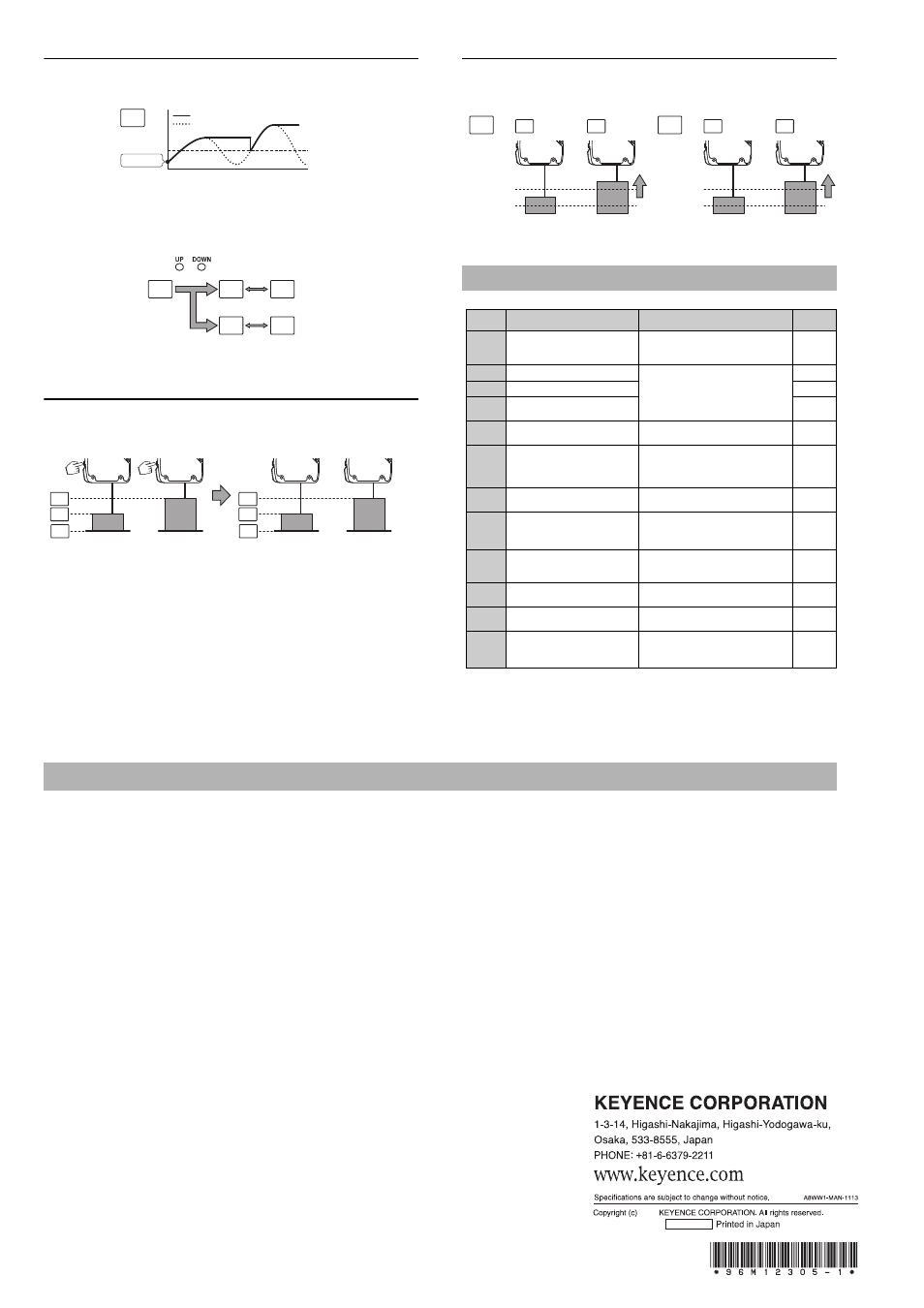
ON
Clamp function OFF
Upper limit
of detection
Setting value
Upper limit
of detection
Setting value
OFF
ON
QP
Q((
* It is invalid when datum calibration is
performed or transmission is turned off.
Warranties and Disclaimers
2012
12305E 1014-1b 96M12305