General troubleshooting flow chart index – Hardy HI 1769-FC User Manual
Page 58
53
●
●
●
●
●
Chapter 7
Voltage Measurements
Load sensor DC voltage signals are between 0-15 millivolts. Overloads and negative
millivolt readings are not shown as actual readings but 15.3 for over voltage and -0.5 for
negative voltage. You will need to use a multimeter with a 200 or 300 mVDC range to
view the out-of-range voltages. Millivolt/volt equals the output from a load cell per each
volt of excitation. The HI 1769-FC reads the load cell output in mV/V, which provides
higher resolution (4 decimal places). This provides more sensitivity to help you
troubleshoot the condition of the load cell under certain conditions. Load cells are rated
in millivolts/volts. To convert to mV, multiply the mV/V times the sense voltage.
IT Test
If your system has an Integrated Technician Summing Junction box, the IT test can help
identify individual load cell problems up to a maximum of four load cell selections.
Sensor Number
Indicates which sensor is under test. Select the target sensor to be tested.
Warning
Do not install your HI 215IT summing board in areas susceptible to high vibrations. The
relays on the board can chatter and affect your weight readings and the vibration can
crystallize the solder joints.
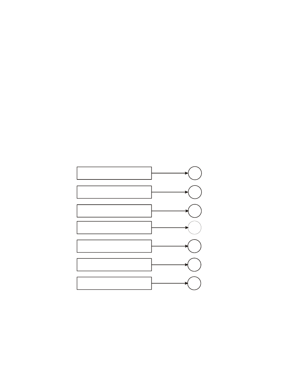
General Troubleshooting Flow Chart Index
B
F
G
H
J
K
Electrical, Mechanical and
Configuration reviews
Trad. Cal - A/D Failure Error
Mechanical Inspection
Electrical Inspection
Load Sensor Installation
A
Drifting or unstable weight readings
Verify individual load sensor operation