Load cell wiring diagrams – Hardy HI 1769-FC User Manual
Page 17
12
●
●
●
●
●
Chapter 3
Load Cell Wiring Diagrams
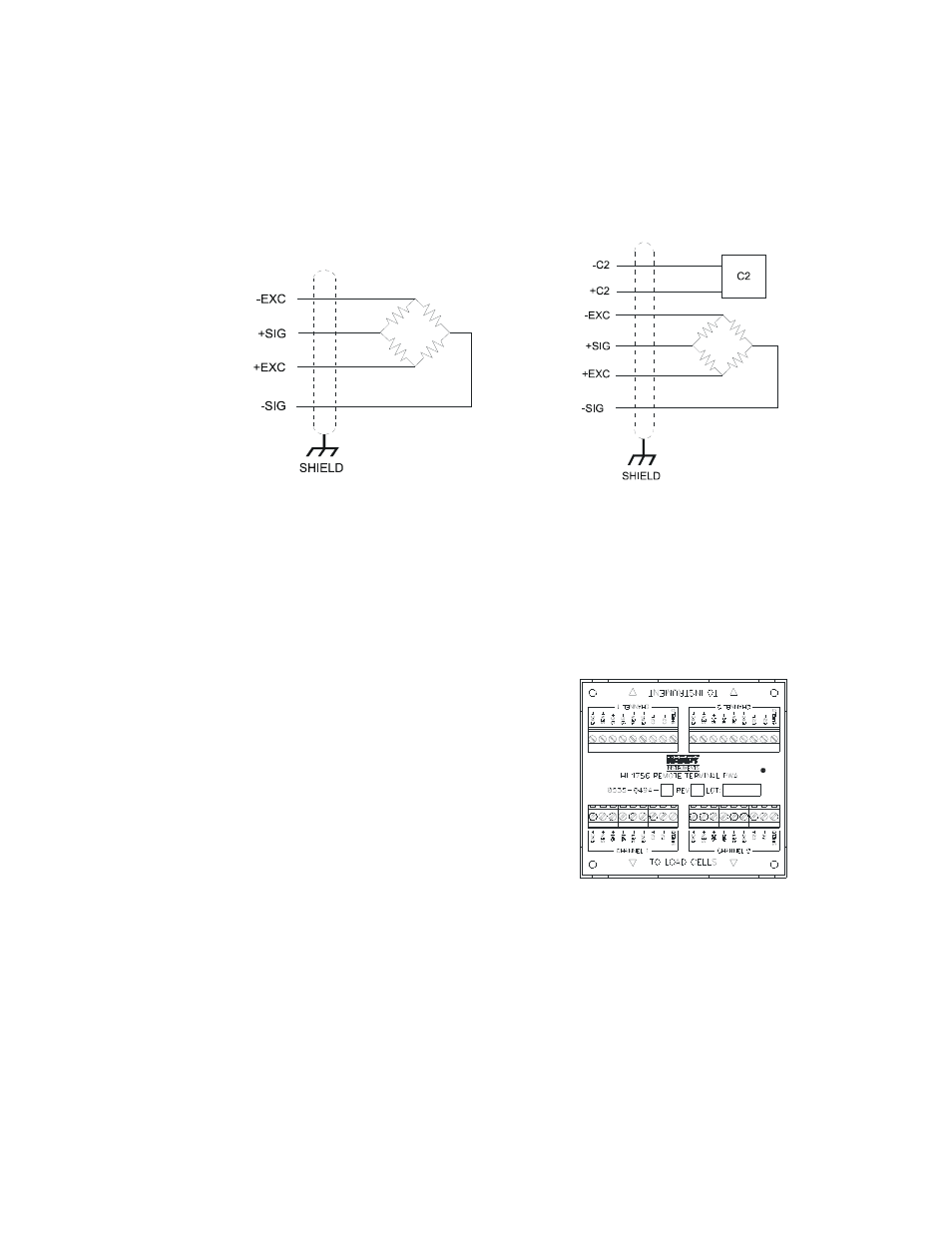
The diagrams below show how Hardy Load Sensor with C2 wiring differs from standard
Load Cell wiring.
Industry standard load cells wiring
Hardy load sensor/c2 wiring
WARNING: LOAD CELL CABLE LENGTH HAS BEEN FACTORED INTO C2 CALIBRATION DATA.
HARDY INSTRUMENTS RECOMMENDS THAT YOU DO NOT CUT YOUR ADVANTAGE® OR
ADVANTAGE LITE® LOAD SENSOR CABLE, AS YOUR C2® ACCURACY WILL BE AFFECTED AND
THE WARRANTY WILL BE VOIDED.
HI 1769 Remote Terminal Assembly (HI 1769-XX-RT)
The Remote Terminal Assembly (RTA)
provides connection points between the cable
assembly from the HI 1769-FC module and
the individual wires from the junction
box(es) or load sensor(s). The RTA comes
with a standard 35 mm Din Rail Mounting
and requires at least a 5” inch long DIN rail
for mounting.
Remote terminal assembly