Jumpers – Hardy HI 1769-FC User Manual
Page 18
13
●
●
●
●
●
Chapter 3
You must have sense jumpers or sense
lines installed to properly reference the
excitation voltage. To properly reference
a C2 calibration, run sense lines and
remove the sense jumper.
NOTE
If your cable run between the J-box and
the controller does not have sense lines,
you will need to jumper the Sense (-) to
the Excitation (-) and the Sense (+) to the
Excitation (+) for one or both channels.
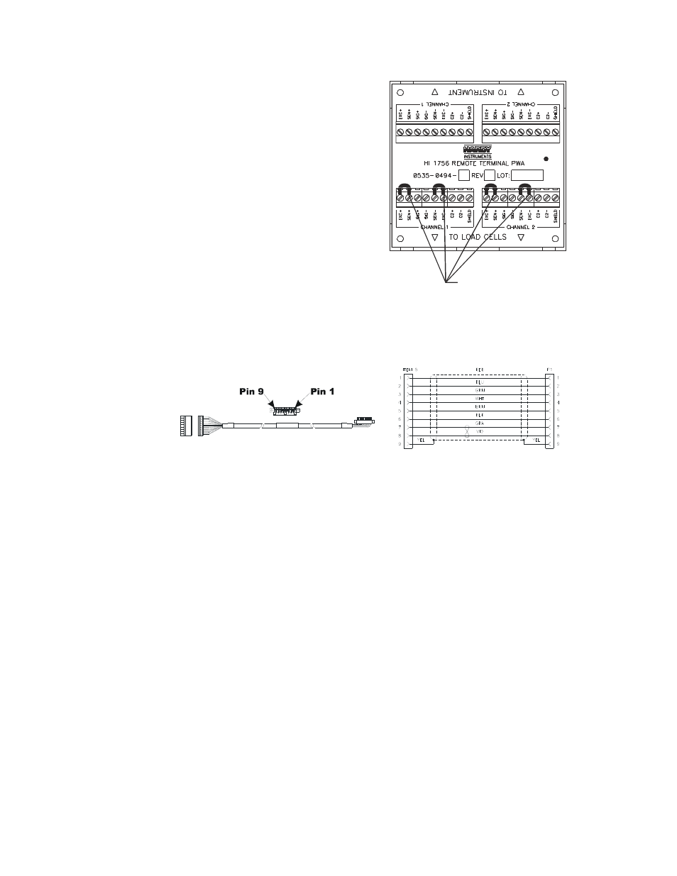
Jumpers
RTA with jumpers for load cells without
sense lines
RTA Cable Assembly and Jumpers
A six-foot cable connects to the HI 1769-FC module.
RTA cable assembly - HI 1769WS
RTA cable schematic
For CE requirements you will need to install an EMI suppression core around the multi-
strand portion of the RTA cable.
Step 1: There should be enough of the individual strands of wire exposed to install the
suppression core. If there is not enough room, remove enough of the cable cover until
you can place the suppression core around all the wire strands.
Step 2: Place the suppression core as close to the module door as possible and still be able to
close the door
Step 3: To open the suppression core place a small slotted screw driver behind the latch and pry
the latch sway from the body of the core until it clears both catches.