Doepfer DIY Synth do-it-yourself analog synthesizer User Manual
Page 22
DIY Synth Kit
Page 22
User's Guide
Application idea: In each circuit a variable resistor can replaced by an LDR (light depending
resistor). For an LDR the resistance value depends upon the illumination and ranges from
some MOhm (dark state) to some hundred Ohm (bright illuminated state). For example the
decay or slew time can be controlled by an LDR that is shadowed by the hand (instead of or
additional to the usual manual control). Even the LFO or ADSR LED can be used to
illuminate the LDR causing a parameter change that depends upon the LED brightness. In
addition the hand can be used to shadow the LED from the LDR.
Other applications of potentiometers
Another application is the usage of a potentiometer to adjust the shares of two signals, e.g.
lowpass and highpass of the VCF (or sawtooth and rectangle of the VCO):
In the upper position the lowpass appears at the center terminal of the potentiometer, in the
lower position the highpass. In between a mixture of lowpass and highpass appears and in
the center position of the control one obtains a notch filter. A linear 10…100k potentiometer
is recommended. For higher resistance values of the potentiometer an additional buffer is
recommended to avoid level changes while operating the control (center terminal of the
potentiometer connected to buffer input).
Controlling the ADSR parameters
The ADSR parameter Attack and Release are controlled by variable logarithmic 1M resistors
as mentioned on the preceding page. These two potentiometers are simply connected to the
terminals ATTACK CCW, ATTACK CENTER and RELEASE CENTER of JP4, and
RELEASE CCW of JP5. CCW is the counterclockwise terminal, CENTER the center
terminal.
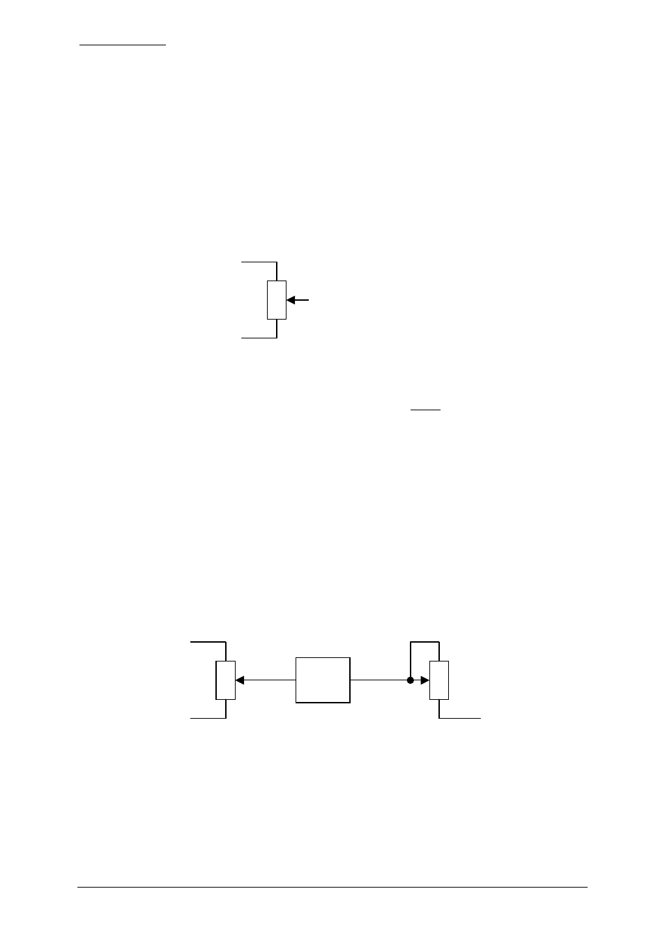
The potentiometers controlling Sustain and Decay are connected in that way:
For a better ADSR operation it is recommended to insert the buffer between the center
terminal of the sustain control and the center terminal of the decay control. The ADSR will
even work without the buffer. But then the envelope waveform is not as expected for short
decays as the 50k sustain potentiometer is loaded during the decay state.
Lowpass/notch/
highpass out
VCF lowpass
VCF highpass
DECAY CCW
(JP4)
SUSTAIN CW
(JP4)
SUSTAIN CCW
(JP4)
Sustain Control
(50k linear)
Decay Control
(1M log)
Buffer
In
(JP5)
Out
(JP5)