Doepfer DIY Synth do-it-yourself analog synthesizer User Manual
Page 16
DIY Synth Kit
Page 16
User's Guide
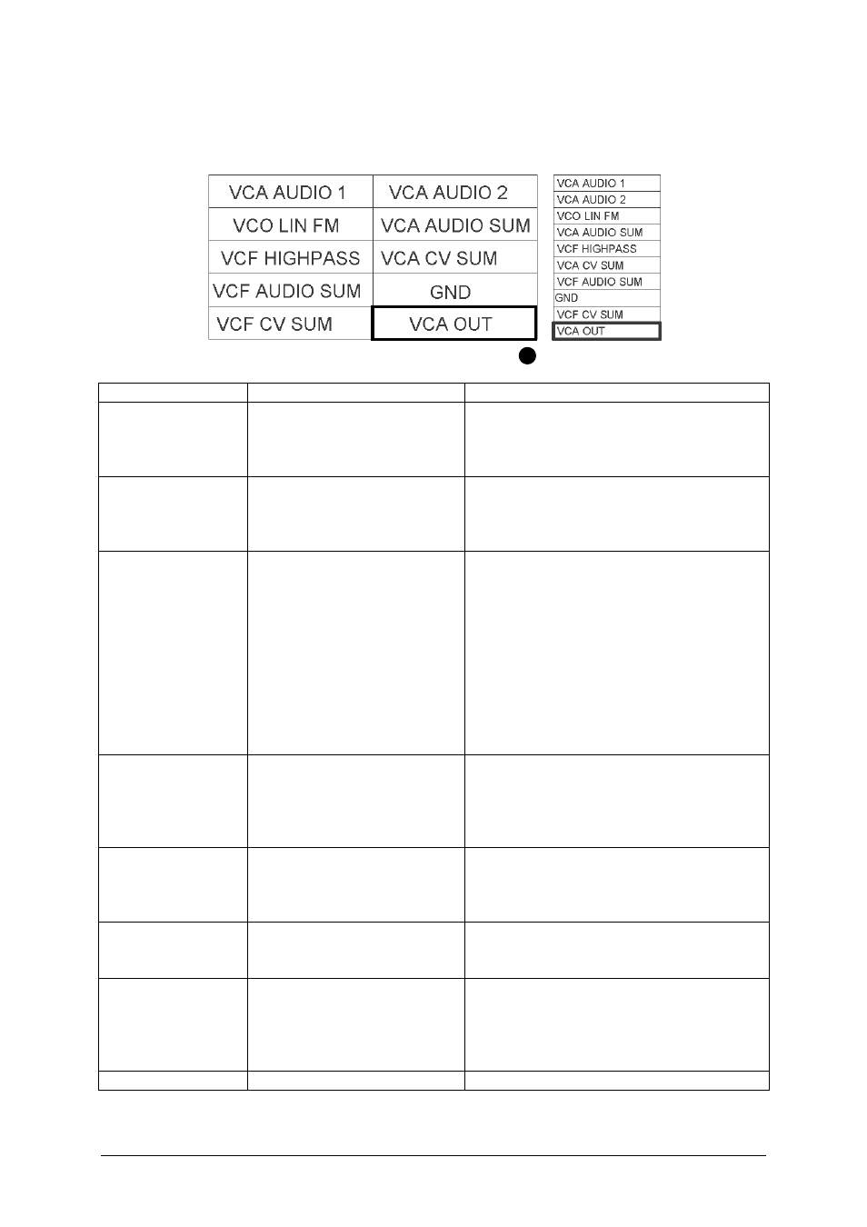
JP7: VCO, VCF and VCA connections
JP7 contains some VCO, VCF and VCA terminals.
pin header top view
ribbon cable
Function
Explanation
Remark / Recommendation
VCA AUDIO IN 1
VCA audio input 1
Usually connected to a socket that is
normalled to one of the VCF outputs
(usually low pass or to the
lowpass/notch/highpass control)
VCA AUDIO IN 2
VCA audio input 2
Usually connected to a socket that is
normalled to one of the other VCF
outputs or directly to one of the VCO
(bypassing the VCF)
VCO LIN FM
VCO linear FM input
Allows linear control of the VCO
frequency (down to zero Hz because it's
DC coupled), the characteristic is
inverted (i.e. increasing the control
voltage at this input reduces the
frequency and vice versa, the VCO stops
when about +1.2 V are applied), usually
connected to a socket labelled "linear
FM" with attenuator (internal summing
resistor is 100k, adding another 100k
serial resistor halves the sensitivity)
VCA AUDIO SUM
VCA audio summing input
Can be used to add audio inputs to the
VCA, required only if the number of VCA
audio inputs is not sufficient, serial
resistor 47k required for same sensitivity
as VCA AUDIO IN 1/2
VCF HIGHPASS
VCF highpass Output
Usually connected to a socket labelled
"VCF Highpass", can be connected
additionally to a potentiometer for
lowpass/notch/ highpass control
VCA CV SUM
Control voltage summing
input for VCA loudness
Required only if one VCA CV input is not
sufficient, serial resistor 220k required for
same sensitivity as VCA CV (see JP3)
VCF AUDIO SUM
VCF audio summing input
Can be used to add audio inputs to the
VCF, required only if the number of VCF
audio inputs is not sufficient, serial
resistor 47k required for same sensitivity
as VCF AUDIO IN (see JP2)
GND