Doepfer DIY Synth do-it-yourself analog synthesizer User Manual
Page 13
User's Guide
page 13
DIY Synth Kit
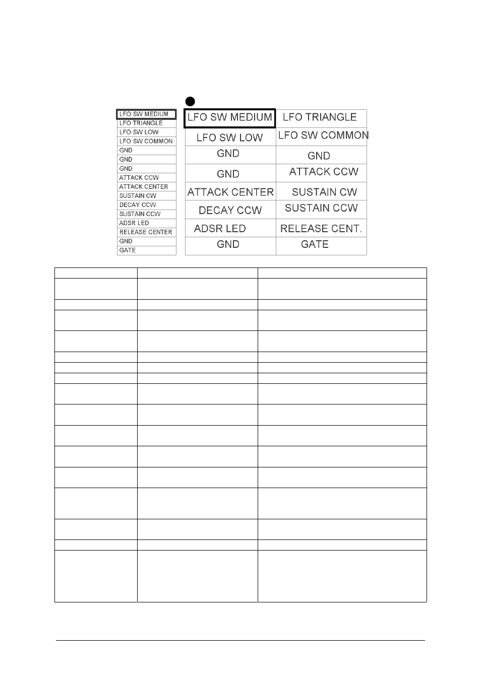
JP4: LFO and ADSR connections
JP4 contains some LFO and ADSR terminals.
ribbon cable
Pin header top view
Function
Explanation
Remark / Recommendation
LFO SW MEDIUM
LFO range switch medium
position
Usually connected to the terminal of a
1-0-1 toggle switch
LFO TRIANGLE
LFO triangle output
about 10V level (+/- 5V)
LFO SW SLOW
LFO range switch low
position
Usually connected to the terminal of a
1-0-1 toggle switch
LFO SW
COMMON
LFO range switch common
terminal
Usually connected to the center terminal
of a 1-0-1 toggle switch
GND
GND
GND
ATTACK CCW
CCW terminal of the ADSR
attack control
Usually connected to the CCW terminal
of the attack control (1M log)
ATTACK CENTER Center terminal of the ADSR
attack control
Usually connected to the center terminal
of the attack control (1M log)
SUSTAIN CW
CW terminal of the ADSR
sustain control
Usually connected to the CW terminal of
the sustain control (50k lin)
DECAY CCW
CCW terminal of the ADSR
decay control
Usually connected to the CCW terminal
of the decay control (1M log)
SUSTAIN CCW
CCW terminal of the ADSR
sustain control
Usually connected to the CCW terminal
of the sustain control (50k lin)
ADSR LED
ADSR LED display
Usually connected to the anode (plus) of
a LED. The cathode of the LED is
connected to GND.
RELEASE
CENTER
Center terminal of the ADSR
release control
Usually connected to the center terminal
of the release control (1M log)
GND
GATE
ADSR gate input
Usually connected to the gate input
socket, min. +5V gate level required, the
socket can be normalled e.g. to the
rectangle output of the LFO (LFO
triggering of the ADSR)