Doepfer DIY Synth do-it-yourself analog synthesizer User Manual
Page 11
User's Guide
page 11
DIY Synth Kit
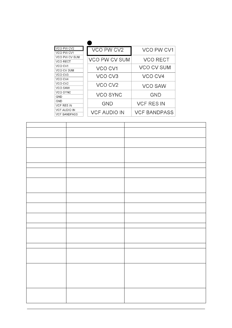
JP2: VCO and VCF connections
JP2 contains some VCO and VCF terminals.
ribbon cable
pin header top view
Function
Explanation
Remark / Recommendation
VCO PW CV2
Control voltage input #2 for
rectangle pulsewidth
Range about 0…+5V, recommended for
PWM input (socket with attenuator)
VCO PW CV1
Control voltage input #1 for
rectangle pulsewidth
Range about 0…+5V, recommended for
PW manual control
VCO PW CV SUM Control voltage summing
input for rectangle
pulsewidth
Required only if the number of CV inputs
for pulsewidth has to be increased, serial
resistor 100k recommended for 0…+5V
VCO RECT
VCO rectangle output
about 5V level (+/- 2.5V), DC coupled
VCO CV1
Control voltage input #1 for
VCO frequency
Sensitivity: 1V/octave, e.g. for manual
frequency control
VCO CV SUM
Control voltage summing
input for VCO frequency
Required only if the number of frequency
CV inputs is not sufficient, serial resistor
100k required for 1V/octave
VCO CV3
Control voltage input #3 for
VCO frequency
Sensitivity: 1V/octave, e.g. for CV input
socket
VCO CV4
Control voltage input #4 for
VCO frequency
Sensitivity: 1V/octave, e.g. for CV input
socket
VCO CV2
Control voltage input #2 for
VCO frequency
Sensitivity: 1V/octave, e.g. for FM input
(socket with attenuator)
VCO SAW
VCO sawtooth output
about 6V level (+/- 3V), AC coupled
VCO SYNC
Hard Sync Input
Negative slope causes a sawtooth reset
(rectangle or sawtooth input required,
min. level 5V required)
2 x GND
VCF RES IN
VCF resonance connector
Has to be wired to the VCF Bandpass
output via attenuator (resonance control,
recommended value 50...100k linear)
VCF AUDIO IN
VCF audio input
Usually connected to one of the VCO
outputs via attenuator (for clipping/
distortion control), if both VCO
waveforms have to be mixed the VCF
AUDIO SUM has to be used (see JP7)
VCF BANDPASS
VCF bandpass Output
Usually connected to a socket labelled
"VCF Bandpass", also required for
resonance control (VCF RES IN)