Doepfer DIY Synth do-it-yourself analog synthesizer User Manual
Page 14
DIY Synth Kit
Page 14
User's Guide
Remark: Several gate signals can be combined via diodes and connected to the gate input.
Another possibility is to connect the switching contact of the gate socket to the rectangle
output of the LFO. In this case the ADSR is triggered automatically by the LFO unless
another gate signal is connected to the gate socket.
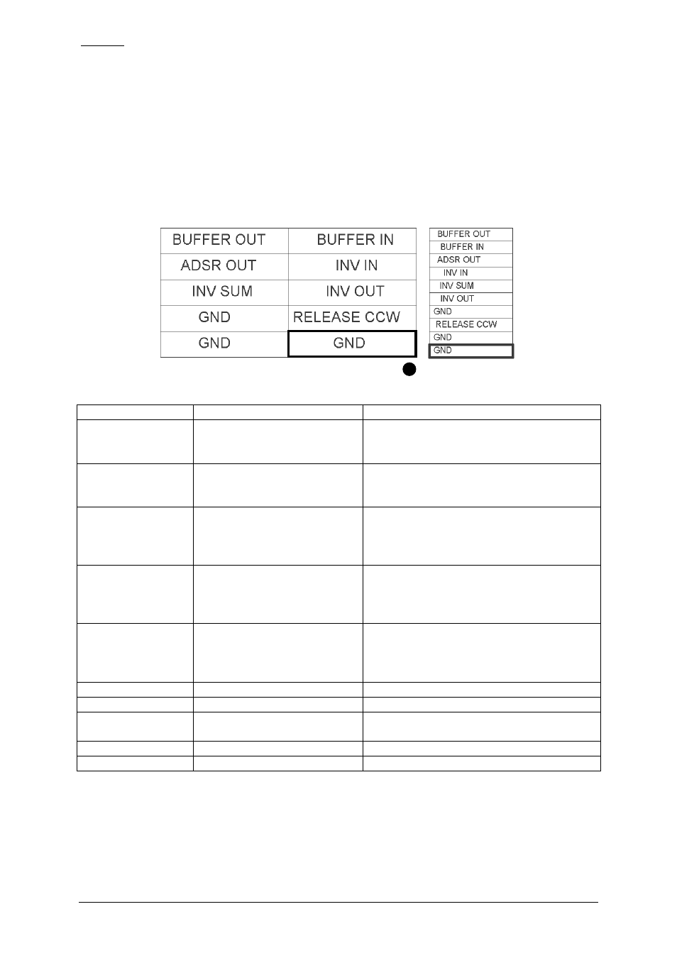
JP5: LFO and ADSR connections
JP5 contains some ADSR, Buffer and Inverter/Mixer terminals.
pin header top view
ribbon cable
Function
Explanation
Remark / Recommendation
BUFFER OUT
Output of the buffer
Usually connected to the center terminal
of the ADSR decay control for best
ADSR operation
BUFFER IN
Input of the buffer
Usually connected to the center terminal
of the ADSR sustain control for best
ADSR operation
ADSR OUT
ADSR output
Typ. 0…+8V level, usually connected to
the ADSR output socket, can be
normalled to the FM/AM inputs of the
VCF and VCA
INV IN
Inverter input
Can be used to invert a signal (e.g.
ADSR), if the INV SUM is used the
inverter unit can be used also for mixing
of CV or audio signals
INV SUM
Inverter summing input
Required if the inverter should be used
as a mixer, serial resistor(s) 100k
recommended for same sensitivity as
INV IN
INV OUT
Inverter output
GND
RELEASE CCW
CCW terminal of the ADSR
release control
Usually connected to the CCW terminal
of the release control (1M log)
GND
GND