Doepfer DIY Synth do-it-yourself analog synthesizer User Manual
Page 15
User's Guide
page 15
DIY Synth Kit
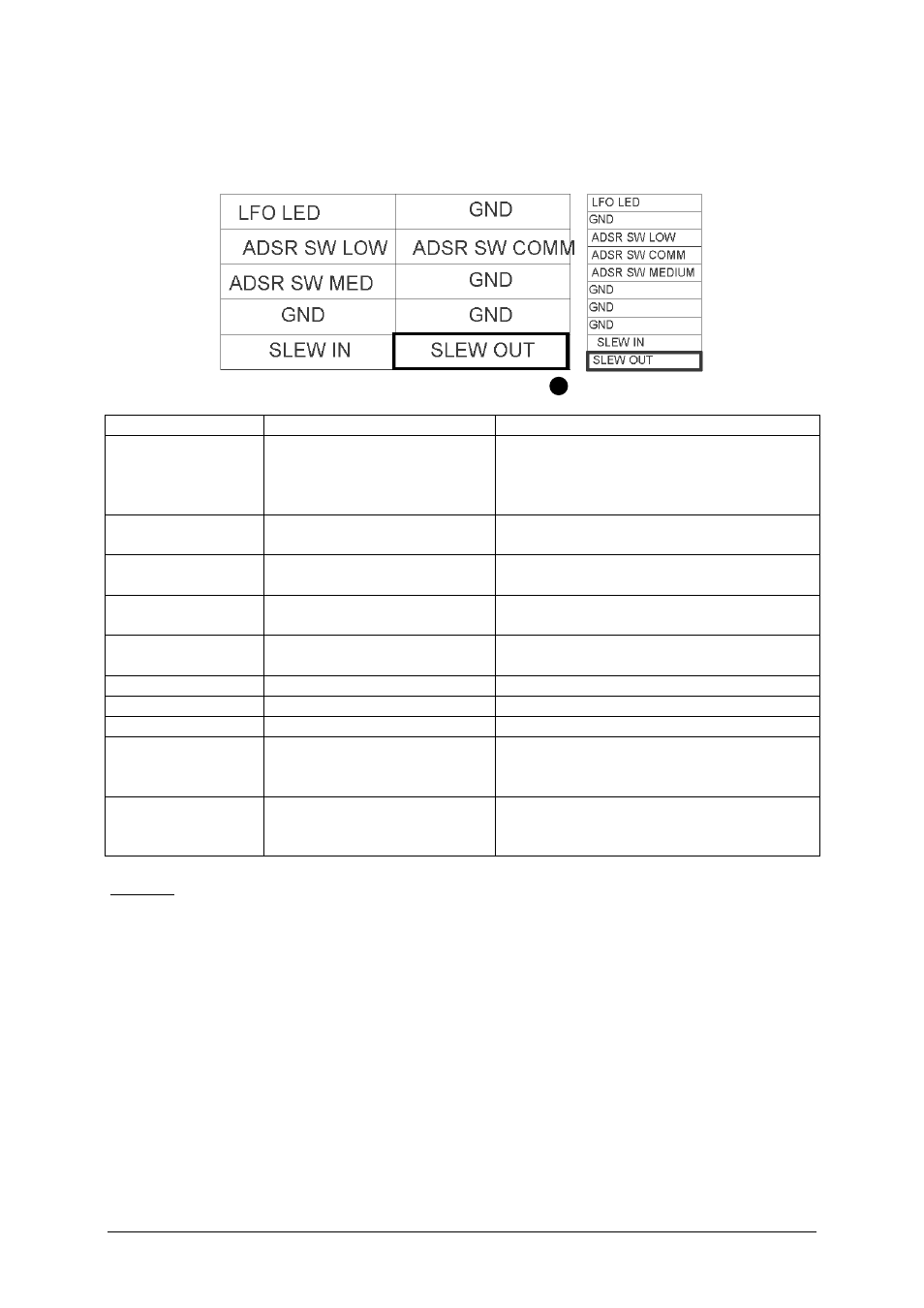
JP6: LFO, ADSR and Slew Limiter connections
JP6 contains some ADSR, LFO and Slew limiter terminals.
pin header top view
ribbon cable
Function
Explanation
Remark / Recommendation
LFO LED
LFO LED display
Usually connected to a dual color LED.
The second terminal of the LED is
connected to GND (e.g. the following
wire).
GND
e.g. for the second terminal of the LFO
LED
ADSR SW SLOW
ADSR range switch low
position
Usually connected to the terminal of a
1-0-1 toggle switch
ADSR SW COMM
ADSR range switch common
terminal
Usually connected to the center terminal
of a 1-0-1 toggle switch
ADSR SW
MEDIUM
ADSR range switch medium
position
Usually connected to the terminal of a
1-0-1 toggle switch
GND
GND
GND
SLEW IN
Input of the slew limiter
Usually connected to the slew source
(e.g. CV for VCO) via a 1M...5M log
potentiometer for slew control
SLEW OUT
Output of the slew limiter
Can be connected e.g. to one of VCO CV
inputs to have available the portamento
function for this input
Remark: If a longer maximal slew time is wanted the value of the slew capacitor C21 (220nF)
can be increased, e.g. by soldering another capacitor in parallel to C21. But we have to point
out that in this case the warranty is void. As C21 is connected between SLEW IN and GND
the additional capacitor can be placed even outside the DIY SYNTH board.
If no slew limiter is required the slew limiter unit can be used as a non-inverting buffer. For
this the smoothing capacitor C21 should be removed.