Directional control assembly – Cub Cadet 310-3000 User Manual
Page 32
28
310-3000 IHT
DIRECTIONAL CONTROL
ASSEMBLY
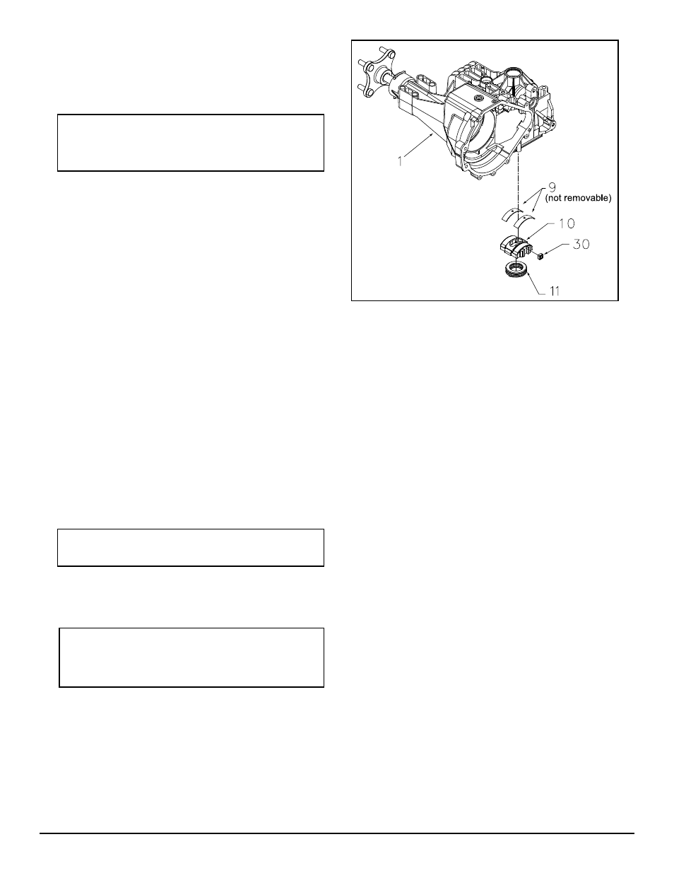
Refer to Figure 18.
NOTE: The Motor/Center Section/Pump
Assembly must be disassembled before
this procedure can be completed.
DISASSEMBLY
1. Remove swashplate assembly (10). Dis as -
sem ble swashplate assembly by removing
thrust bearing (11) from swashplate (10).
The thick race of thrust bearing must face
pis tons.
2. Remove slot guide (30).
INSPECTION
1. Visually inspect (in place) the two cradle
bear ings (9), which are staked in upper
housing. Do not remove the Cradle Bear-
ings (9) from housing (1).
ASSEMBLY
1. Install slot guide (30).
2. As
sem ble swashplate as sem bly (10) by in-
stall ing thrust bearing (11) into swashplate
(10).
Note: As sem ble thrust bear ing with thick
race fac ing pistons.
3. Install swashplate assembly (10) into main
housing (1). The swashplate (10) will couple
with slot guide (30).
NOTE: When in stall ing swashplate as-
sem bly (10), use fl at head screwdriver
to hold slot guide (30) in place.
REF. Part Name
1 Main Housing
9 Cradle Bearing
10 Variable Swashplate
11 Thrust Bearing
30 Slot Guide
Figure 18. Directional Control Assembly