Brake assembly, Disassembly – Cub Cadet 310-3000 User Manual
Page 17
310-3000 IHT
13
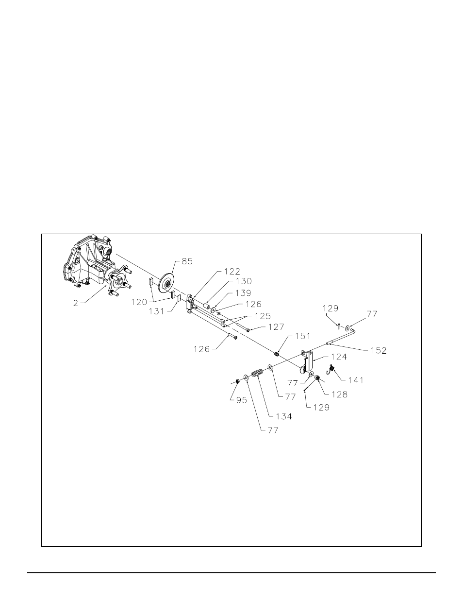
BRAKE ASSEMBLY
Refer to Figures 6 and 7.
DISASSEMBLY
The following procedure is for model 324-3000.
Reference microfi che for other models.
1. Remove lock nut (95), washer (77), brake
spring (134), and washer (77) from brake
pull rod (152).
2. Remove cotter pin (129), and washer (77)
from brake pull rod (152).
3. Remove brake pull rod (152) and set
aside.
4. Remove the cotter pin (129), castle nut
(128), and wash er (77).
5. Remove brake arm (124), and brake arm
bias spring (141).
6. Remove brake anti-drag compression spring
(151), and two brake pins (125).
7. Remove upper nut (127), lock washer (126),
wash er (139), and spacer (130) which se-
cure brake yoke as sem bly (122).
8. Remove lower nut (127), and lock washer
(126) se cur ing brake yoke assembly
(122).
9. Remove brake yoke assembly (122), puck
plate (131), and outer brake puck (120).
10. Remove brake disc (85), and inner brake
puck (120).
Figure 6. Brake Assembly
REF. Part Name
127 Nut
128 Castle
Nut
129 Cotter
Pin
130 Spacer
131 Puck
Plate
134 Brake
Spring
139 Washer
141 Brake Arm Bias Spring
151 Anti-Drag Compression Spring
152 Brake Pull Rod
REF. Part Name
2 Right Hand Housing As sem bly
77 Washer
85 Brake Disk
95 Lock Nut
120 Brake
Puck
122 Brake
Yoke
Assembly
123 Square Head Bolt
124 Brake
Arm
125 Brake
Pin
126 Lock
Washer