Cub Cadet 310-3000 User Manual
Page 18
14
310-3000 IHT
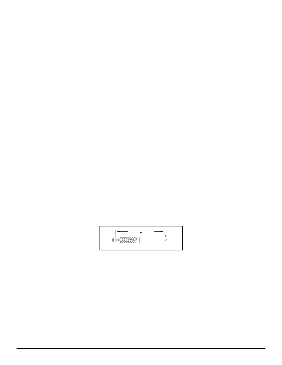
Figure 7. Brake Pull Rod Assembly Ad just ment
INSPECTION
1. Inspect the brake pucks (120) for excessive
wear.
2. Replace with new if necessary.
ASSEMBLY
1. Install inner brake puck (120), and brake
disc (85).
2. Assemble the brake yoke assembly, by in-
stall ing puck plate (131), outer brake puck
(120) into brake yoke (122).
3. Install the brake yoke assembly onto two
mounting studs on housing assembly (2).
Use of a feeler gage (0.015”) (.381 mm)
may be help ful in re tain ing the brake yoke
assembly at this step.
4. Install at upper bolt spacer (130), washer
(139), lock wash er (126), and nut (127).
5. Install at lower bolt lock washer (126), and
nut (127) to secure the brake yoke as-
sem bly.
6. Install brake anti-drag compression spring
(151), and two brake pins (125).
7. Install brake arm (124) onto brake yoke as-
sem bly.
8. Install washer (77), and castle nut (128).
9. Insert a (0.015”) (.381 mm) feeler gage be-
tween brake disc (85) and top brake puck
(120). Adjust the brake by turning castle nut
(128) until it is snug but not tight against the
feeler gage. (The brake gap must be ad-
just ed to a (0.015”) (.381 mm) clearance.
10. Install cotter pin (129) to secure castle nut
(128).
11. Install brake arm bias spring (141) to brake
arm (124) and top brake arm bolt.
12. Install brake pull rod (152) into brake arm
(124) and ac tu at ing arm (35).
13. Secure brake rod (152) to actuating arm
(35) by in stall ing washer (77) and cotter
pin (129).
14. Secure brake pull rod (152) to brake arm by
in stall ing wash er (77), brake spring (134),
wash er (77), and lock nut (95). Set to the
di men sion shown in Figure 7.
5.64 + 0.06
BRAKE ROD ASSEMBLY