Lower housing/filter/ manifold assembly – Cub Cadet 310-3000 User Manual
Page 26
22
310-3000 IHT
REF. Part Name
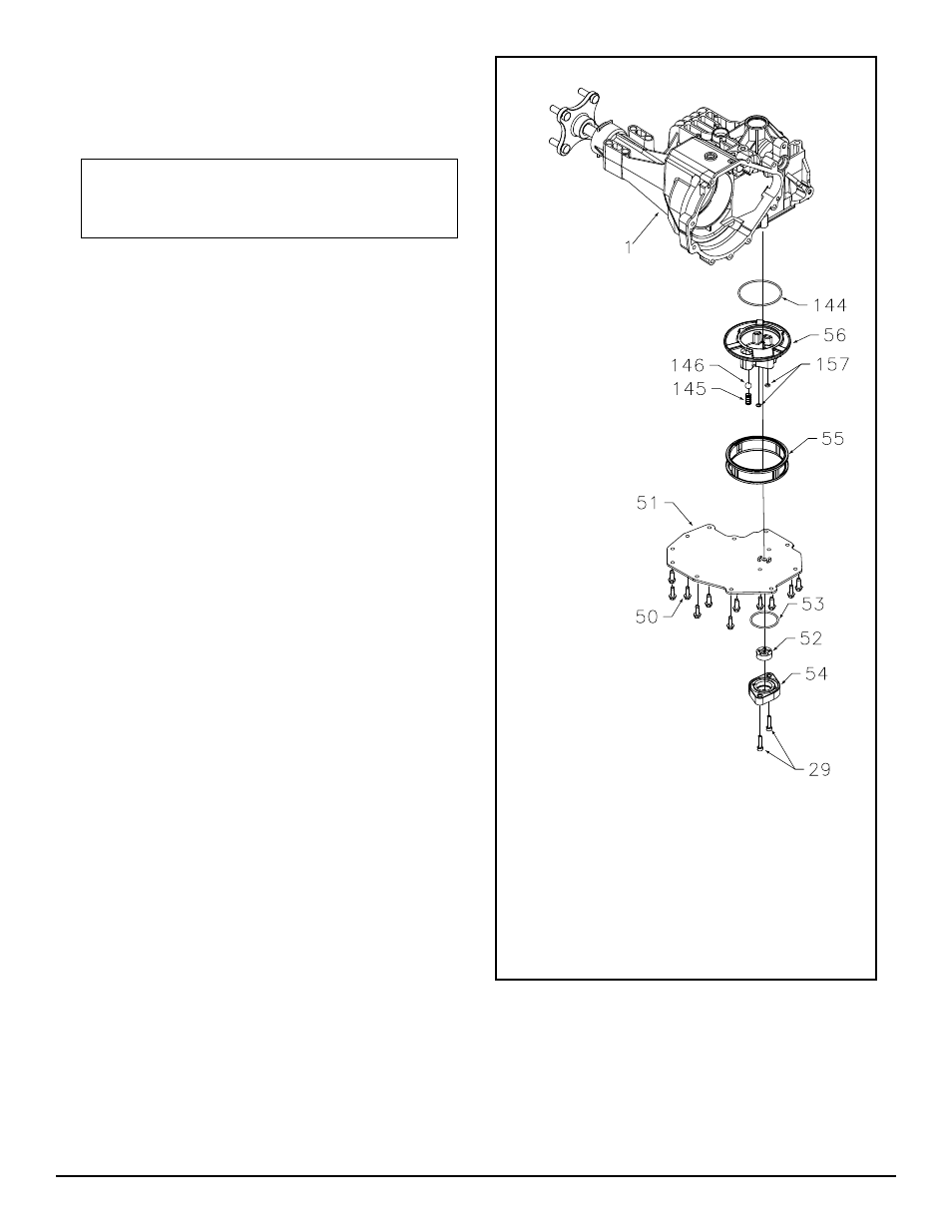
1 Main Housing
29 Capscrew
49 Not Used
50 Screws
51 Lower Cover
52 Gerotor Assembly
53 O-Ring
54 Gerotor Cover
REF. Part Name
55 Filter
56 Charge Manifold
144 O-Ring
145 Spring
146 Ball
156 Manifold
O-Ring
157 Screw
O-Ring
Fig ure 14. Lower Housing/Filter/Man i fold Assembly
LOWER HOUSING/FILTER/
MANIFOLD ASSEMBLY
Refer to Figure 14.
NOTE: Charge Pump assembly must be
removed before the following steps can
be performed.
DISASSEMBLY
1. Remove the eleven housing screws (50) and
low er cover (51), and remove sealant.
2. Remove screw O-rings (157).
3. Remove spring (145) and ball (146).
4. Remove fi lter (55) and charge manifold
(56).
5. Remove O-ring (144).
INSPECTION
1. Inspect fi lter (55) and manifold (56), replace
if necessary.
2. Inspect O-ring (144) and screw O-rings
(157).
ASSEMBLY
1. Install O-ring (144) onto center section as-
sem bly (3), re fer to Figure 134
2. Install fi lter (55) and charge manifold (56).
3. Install spring (145) and ball (146).
4. Install screw O-rings (157).
5. Dry fi t lower cover (51) on housing, using
screws (29) to align cover and manifold
(56).
6. Remove screws (29) and cover (51). Apply
sealant (79) to lip of main hous ing (1).
7. Reinstall cover (51) and screws (29), ref-
er ence Table 5, Page 13.
8. Secure lower cover (51) to main housing
(1) by in stall ing the eleven housing screws
(50), reference Table 5, Page 13.