Return to neutral setting hand control warning, Warning – Cub Cadet 310-3000 User Manual
Page 12
8
310-3000 IHT
RETURN TO NEUTRAL SETTING
HAND CONTROL
WARNING
POTENTIAL FOR SERIOUS INJURY
Certain procedures re quire the vehicle
en gine to be operated and the vehicle
to be raised off of the ground. To pre-
vent pos si ble injury to the ser vic ing
tech ni cian and/or by stand ers, in sure
the ve hi cle is prop er ly se cured.
The return to neutral mechanism on the
trans mis sion is designed to set the di rec -
tion al con trol into a neutral position when the
vehicle park ing brake is en gaged. Fol low the
procedures below to properly adjust the return
to neutral mechanism on the transaxle:
1. Confi rm the transaxle is in the operating
mode (bypass disengaged). Raise the
ve hi cle’s drive tires off the ground to allow
free ro ta tion.
NOTE: It may be necessary to remove
the drive tire from the axle hub to ac-
cess the linkage control and the trans-
axle control arm.
2. Remove the Original Equipment Man u -
fac tur er’s (OEM’s) control linkage at the
control arm. Refer to Figure 4.
3. Remove the cotter pin and washer se cur ing
the brake pull rod to the return actuating
arm. Remove the brake pull rod from the
return actuating arm. Re fer to Figure 4.
WARNING
Do not attempt any adjustments with the
engine running. Use extreme caution
while inspecting all vehicle linkage!
Follow all safety procedures outlined in
the vehicle owner’s manual!
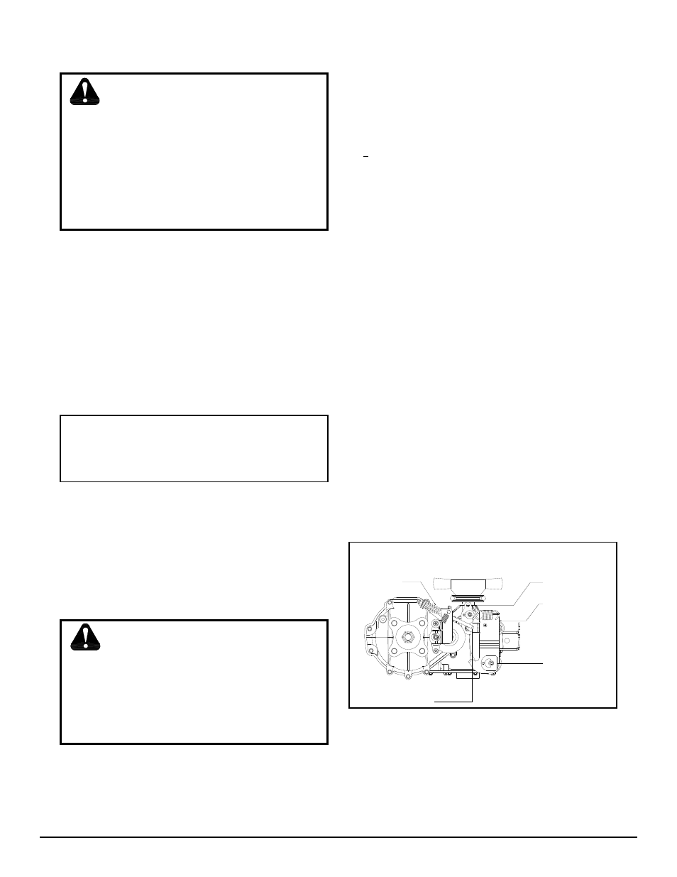
Figure 4. Return to Neutral, Hand Control
4. Apply the vehicle brake, start the engine and
increase the throttle to full engine rpm.
5. Check for axle rotation. If the axles do not
ro tate, go to Step 6. If the axles rotate, go
to Step 7.
6. Stop the vehicle engine. Adjust the OEM
link age according to the OEM manual. Re-
check ac cord ing to step 4 and 5. Stop the
vehicle en gine. Re place the brake pull rod
onto the re turn ac tu at ing arm. Install the
washer and a new cot ter pin securing the
brake pull rod to the ac tu at ing arm. Refer
to Figure 4.
7. Note the axle directional movement . Stop
the vehicle’s engine. Loosen the adjusting
puck screw until the puck can be rotated.
Rotate the adjusting puck the opposite di-
rec tion of the wheel rotation on the control
link age side in 5 degree increments. Tighten
the adjusting puck screw. Refer to Table 5.
Required Torque Values, Page 13. Re check
ac cord ing to step 4 and 5. Stop the vehicle
en gine. Ad just the OEM linkage according
to the OEM man u al. Recheck according
to Step 4 and 5. Stop the vehicle engine.
Re place the brake pull rod onto the return
ac tu at ing arm. Install the washer and a new
cot ter pin se cur ing the brake pull rod to the
ac tu at ing arm. Refer to Figure 4.
CONTROL ARM
RETURN ACTUATING ARM
ADJUSTING PUCK
BRAKE PULL ROD
COTTER PIN AND WASHER
(HIDDEN)