Checkline TT05 User Manual
Page 13
Series TT05 Digital Torque Testers
User’s Guide
12
RS232/USB Output
Outputs data via the serial and USB ports
Mitutoyo Output
Outputs data via Mitutoyo (Digimatic) through the serial port
Memory Storage
Stores a reading to memory (refer to the Memory section for details)
Any combination of the above functions may be selected.
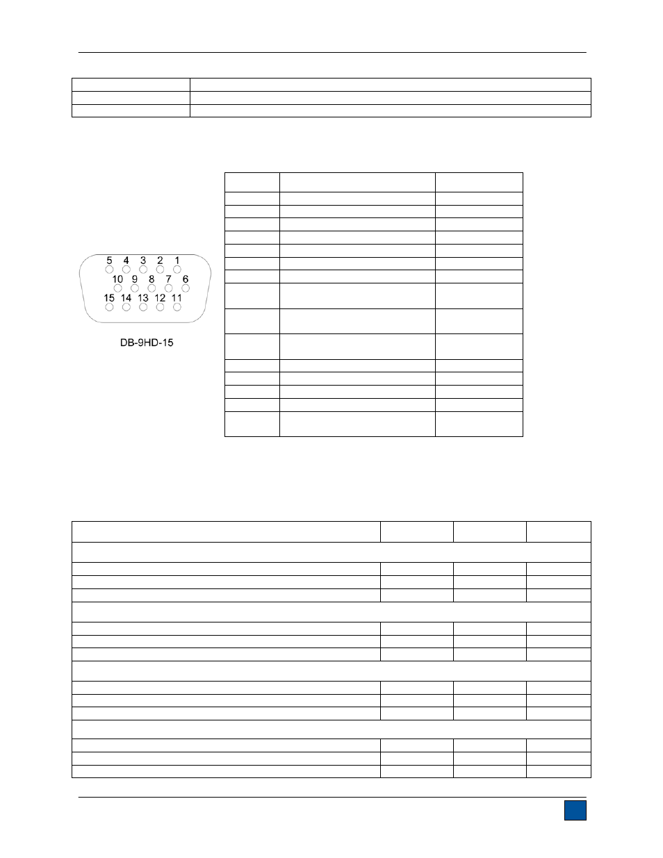
10.6 I/O Connector Pin Diagram (female)
Notes:
1. Mitutoyo and general purpose outputs cannot be activated simultaneously.
2. The set point output assignments depend on several factors described in the table below. Output
functions always reference the primary reading on the display, regardless of the current mode.
Torque
Pin 11
Pin 12
Pin 13
Upper and Lower Set Points are Clockwise
Greater than or equal to upper set point
On
Off
Off
Between upper and lower set points
Off
Off
On
Less than or equal to lower set point
Off
On
Off
Upper and Lower Set Points are Counter-clockwise
Greater than or equal to upper set point
Off
On
Off
Between upper and lower set points
Off
Off
On
Less than or equal to lower set point
On
Off
Off
Upper Set Point is Clockwise, Lower Set Point is Counter-clockwise
Greater than or equal to upper set point, in clockwise
Off
On
Off
Between upper and lower set points
Off
Off
On
Greater than or equal to lower set point, in counter-clockwise
On
Off
Off
Upper Set Point is Counter-clockwise, Lower Set Point is Clockwise
Greater than or equal to upper set point, in counter-clockwise
Off
On
Off
Between upper and lower set points
Off
Off
On
Greater than or equal to lower set point, in clockwise
On
Off
Off
Pin No.
Description
Input / Output
1 Signal
Ground
---
2
Counter-clockwise Overload
Output
3
RS-232 Receive
Input
4 RS-232
Transmit
Output
5 +12V
DC
Output
6 Analog
Output
Output
7 Clockwise
Overload
Output
8
1
Mitutoyo
Clock
Output Bit 2
1
Output
1
9
1
Mitutoyo
Data
Output Bit 0
1
Output
1
10
1
Mitutoyo
Request
Input Bit 3
1
Input
1
11
2
Set Point Pin 1
2
Output
2
12
2
Set Point Pin 2
2
Output
2
13
2
Set Point Pin 3
2
Output
2
14
Do not connect
---
15
1
Mitutoyo
Ready
Output Bit 1
1
Output
1