Checkline ESM301 User Manual
Page 5
Model ESM301 / ESM301L Version 2 Test Stand
User’s Guide
5
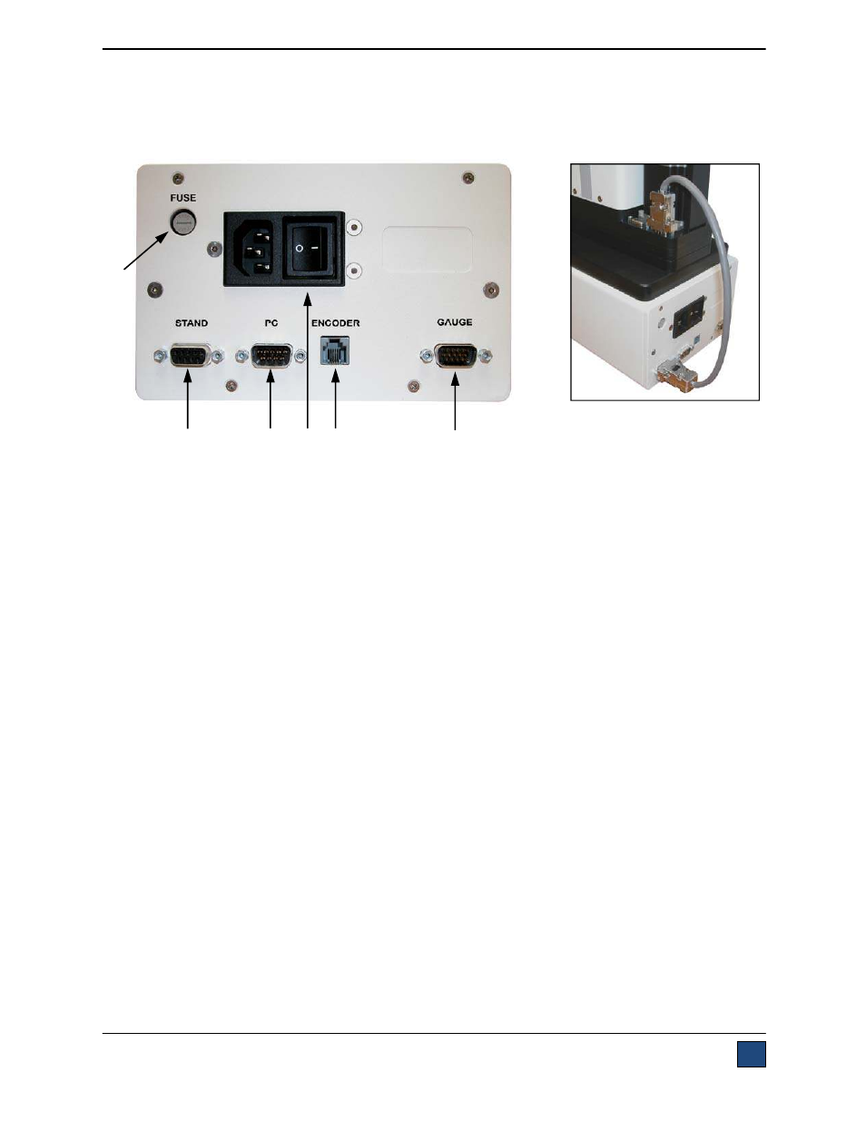
2.2 Setting up the Controller
The power plug and controller cable must be connected to the rear of the controller, as shown in the
illustration below:
1. Fuse
2. Controller Cable Connector
Plug one end of the cable into this connector, and the other end into the connector as shown in
the illustration on the right.
3. PC Output Connector
Outputs force only or force and travel data via RS-232. Also allows for PC control, if appropriate
features are enabled. Plug one end of the 09-1056 serial cable into this connector, and the other
end into a serial connector on a computer.
4. Power Plug Receptacle
Plug the power cord in here.
5. Travel
Indication
Connector
Plug one end of the USB/RJ11 cable into this connector, and the other end into the mini USB
connector in the rear of the crosshead.
6. Force Gauge Cable Connector
Interfaces with a Series 5 or 4 force gauge. Plug one end of the 09-1162 cable into this
connector, and the other end into the gauge.
2.3 Connecting Power
Plug one end of the power cord into its receptacle at the rear of the controller and the other end into a
wall outlet with local earth ground (3-prong connector).
Before turning on power, the following safety checks and procedures should be performed:
1. Never operate the test stand if there is any visible damage to the power cord or the test stand
itself. The ESM301 is powered by 110V/220V. Any contact with this high voltage can cause
serious injury or even death.
2. Ensure that the test stand is kept away from water or any other electrically conductive liquids
2
1
4
3
5
6