2 network topology, 3 operation model, 2 network topology -3 – Panasonic NN46240-710 User Manual
Page 82: 3 operation model -3, Network topology, Operation model
Attention! The text in this document has been recognized automatically. To view the original document, you can use the "Original mode".
Nortel Secure Router 8000 Series
Troubleshooting - VPN___________
3 BGP/MPLS IP VPN troubleshooting
3.1.2 Network topology
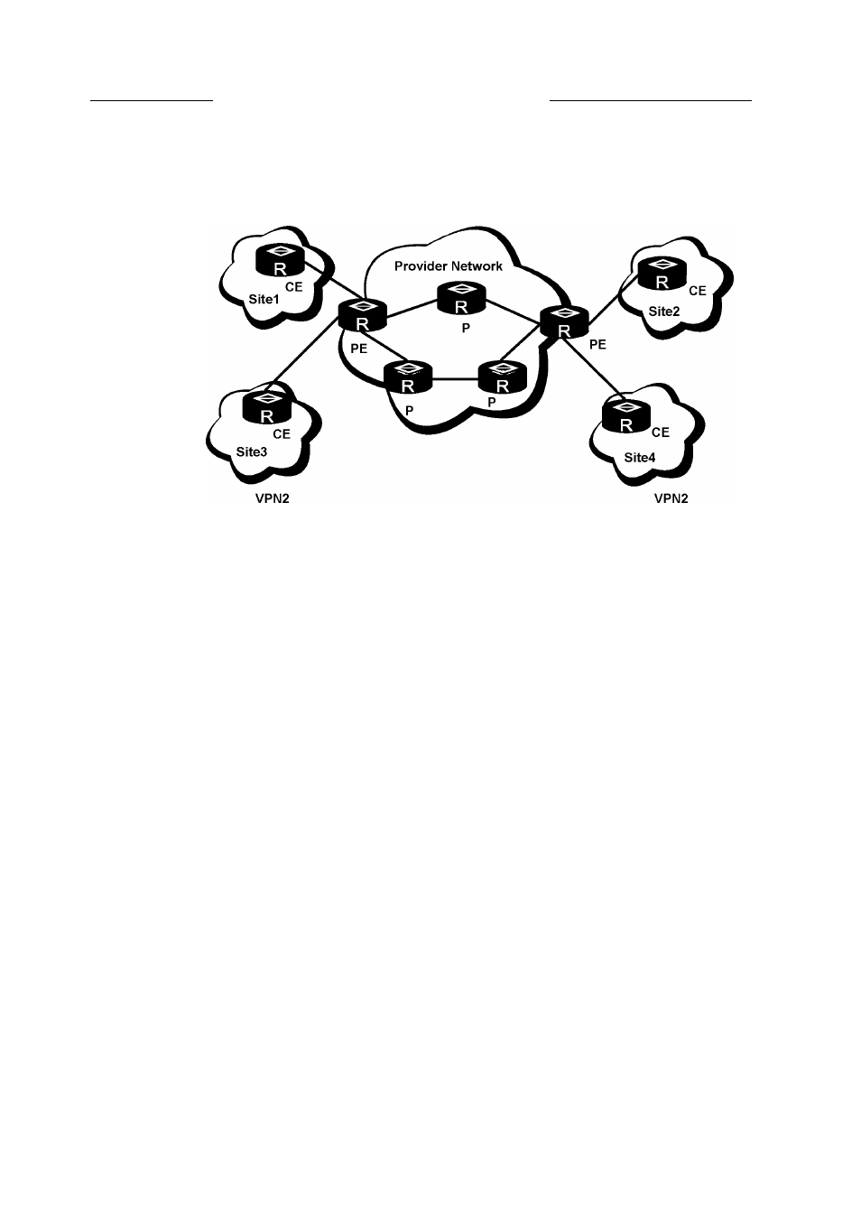
Figure 3-1 BGP/MPLS VPN network topology
VPN1
VPN1
Figure 3-1 shows a basic BGP/MPLS VPN network topology. In a basic BGP/MPLS VPN
network topology, the customer edge (CE) can be a host, switch, or router. An adjacency
establishes between the CE and its directly-connected PE. The CE sends its VPN routes to the
PE and learns remote VPN routes from the PE.
The PE exchanges routing information with the CE through a static route, Routing Information
Protocol (RIP), Open Shortest Path First (OSPF), Intermediate System-to-Intermediate System
(IS-IS) or Exterior BGP (EBGP). Every PE router maintains a VPN routing and forwarding
(VRF) table for every directly-connected site. A PE router can maintain multiple VRFs. You
can associate a VRF with multiple interfaces. After learning local VPN routes from local CEs,
the PE router exchanges them with other peer PEs using Interior BGP (IBGP).
The provider router (P) is a router that exists in the operator network that does not directly
connect with the CE. The P acts as an MPLS Label Switching Router (LSR), used to forward
VPN traffic between PEs. Because the MPLS backbone uses a two-level label stack, the P only
needs to maintain the routes to the PE rather than VPN routing information.
3.1.3 Operation model
The BGP/MPLS VPN uses two types of communication traffic:
•
Control traffic: traffic used to distribute and switch VPN routes, and establish label switch
paths
•
Data traffic: data traffic of users
The process to forward BGP/MPLS VPN traffic is as follows:
•
•
•
Issue 5.3 (30 March 2009)
Nortel Networks Inc.
3-3