Scenario, Fault analysis – Panasonic NN46240-710 User Manual
Page 143
Attention! The text in this document has been recognized automatically. To view the original document, you can use the "Original mode".
Nortel Secure Router 8000 Series
Troubleshooting - VPN___________
4 MPLS L2VPN troubleshooting
4.3.8 Ethernet interconnects with ATM, the VC is up, but the ping
between CEs fails
Scenario
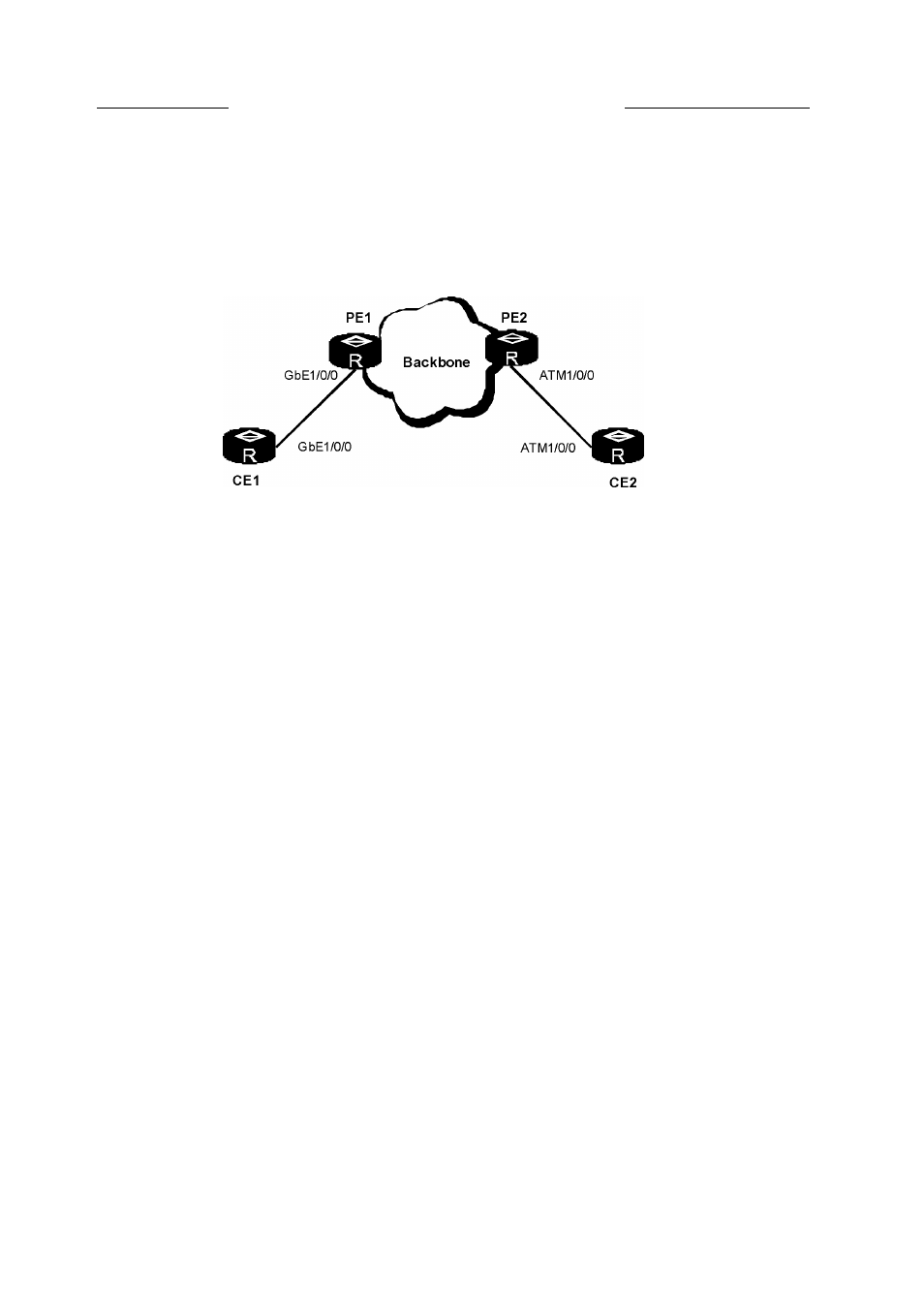
Figure 4-17 Networking diagram
As shown in Figure 4-17, Ethernet interconnects ATM. After Layer 2 VPN IP-interworking is
configured, the VC at both ends is Up, but the ping between CEs fails.
Fault analysis
Check whether the IP address of the two CEs is on the same network segment. The address of
the two ends must be on the same network segment.
Use the display local-ce mac command on PE, and use the display arp command on CE to
check the establishment of ARP entries of the Ethernet link.
If ARP entries are not set up successfully, configure the IP address and the MAC address for the
Ethernet interface of CE on PE and also enable MAC broadcasting on PE. That is, run the
local-ce ip command, the local-ce mac command and the local-ce mac broadcast command
on PE.
For detailed configuration, see
Nortel Secure Router 8000 Series Configuration Guide - VPN
(NN46240-507).
CD NOTE
The IP address configured on PE is that of the corresponding interface on the remote CE.
For ARP entries of the ATM link, you can use one of the two methods:
• Use INARP to generate MAP dynamically. Figure 4-18 shows an example to configure IP
addresses. The configuration is as follows:
[PE2] interface atm1/0/0
[PE2-Atm1/0/0] pvc 100/200
[PE2-atm-pvc-Atm1/0/0-100/200]
[PE2-atm-pvc-Atm1/0/0-100/200]
[CE2] interface atm1/0/0
[CE2-Atm1/0/0] pvc 100/200
[CE2-atm-pvc-Atm1/0/0-100/200]
[CE2-atm-pvc-Atm1/0/0-100/200]
map ip inarp broadcast
ip address 10.1.1.1 255.255.255.0
map ip inarp broadcast
ip address 10.1.1.2 255.255.255.0
Issue 5.3 (30 March 2009)
Nortel Networks Inc.
4-33