Master reset, Interrupts – Cypress CY7C0430BV User Manual
Page 23
CY7C0430BV
CY7C0430CV
Document #: 38-06027 Rev. *B
Page 23 of 37
Master Reset
The QuadPort DSE device undergoes a complete reset by
taking its Master Reset (MRST) input LOW. The Master Reset
input can switch asynchronously to the clocks. A Master Reset
initializes the internal burst counters to zero, and the counter
mask registers to all ones (completely unmasked). A Master
Reset also forces the Mailbox Interrupt (INT) flags and the
Counter Interrupt (CNTINT) flags HIGH, resets the BIST
controller, and takes all registered control signals to a
deselected read state.
[50]
A Master Reset must be performed
on the QuadPort DSE device after power-up.
Interrupts
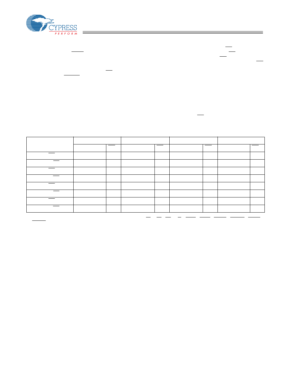
The upper four memory locations may be used for message
passing and permit communications between ports. Table 3
shows the interrupt operation for all ports. For the 1-Mb
QuadPort DSE device, the highest memory location FFFF is
the mailbox for Port 1, FFFE is the mailbox for Port 2, FFFD is
the mailbox for Port 3, and FFFC is the mailbox for Port 4.
Table 3 shows that in order to set Port 1 INT
P1
flag, a write by
any other port to address FFFF will assert INT
P1
LOW. A read
of FFFF location by Port 1 will reset INT
P1
HIGH. When one
port writes to the other port’s mailbox, the Interrupt flag (INT)
of the port that the mailbox belongs to is asserted LOW. The
Interrupt is reset when the owner (port) of the mailbox reads
the contents of the mailbox. The interrupt flag is set in a
flow-through mode (i.e., it follows the clock edge of the writing
port). Also, the flag is reset in a flow-through mode (i.e., it
follows the clock edge of the reading port).
Each port can read the other port’s mailbox without resetting
the interrupt. If an application does not require message
passing, INT pins should be treated as no-connect and should
be left floating.
When two ports or more write to the same
mailbox at the same time INT will be asserted but the contents
of the mailbox are not guaranteed to be valid.
Note:
50. During Master Reset the control signals will be set to a deselected read state: CE
0I
= LBI = UBI = R/WI = MKLDI = MKRDI = CNTRDI = CNTRSTI = CNTLDI =
CNTINCI = V
IH
; CE
1I
= V
IL.
The “I” suffix on all these signals denotes that these are the internal registered equivalent of the associated pin signals.
Table 3. Interrupt Operation Example
Function
Port 1
Port 2
Port 3
Port 4
A
0P1–15P1
INT
P1
A
0P2–15P2
INT
P2
A
0P3–15P3
INT
P3
A
0P4–15P4
INT
P4
Set Port 1 INT
P1
Flag
X
L
FFFF
X
FFFF
X
FFFF
X
Reset Port 1 INT
P1
Flag
FFFF
H
X
X
X
X
X
X
Set Port 2 INT
P2
Flag
FFFE
X
X
L
FFFE
X
FFFE
X
Reset Port 2 INT
P2
Flag
X
X
FFFE
H
X
X
X
X
Set Port 3 INT
P3
Flag
FFFD
X
FFFD
X
X
L
FFFD
X
Reset Port 3 INT
P3
Flag
X
X
X
X
FFFD
H
X
X
Set Port 4 INT
P4
Flag
FFFC
X
FFFC
X
FFFC
X
X
L
Reset Port 4 INT
P4
Flag
X
X
X
X
X
X
FFFC
H