WEATHER GUARD Model 255 EZ-GLIDE® Drop Down Kit, Full, Driver Side User Manual
Page 5
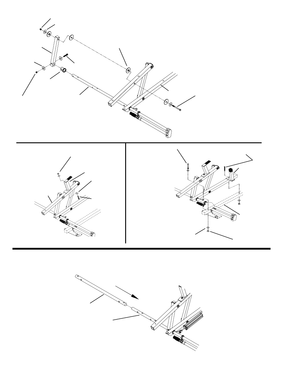
STEPS 2 & 3
Slide a White Plastic Bushing (A) onto
the Rear Drive Tube (B) until it is
butted up to the Lower Rotation Tube
(C). Align holes in the tube and bush-
ing. Slide the Pivot Arm (D) over the
tube and bushing, align holes, and
install the 3/8-16 x 2-1/4" Fastener.
Next install the 5/16-18 x 4-1/2" Fas-
tener with four Flat Plastic (E) bushings
as shown.
(A)
(B)
(D)
* 3/8-16 x 2-1/4"
Hex Hd. Bolt
(2) 3/8" Flat
Washer
3/8-16 Nylon
Lock Nut
5/16-18 x 4-1/2"
Hex Hd. Bolt
(2) 3/8" Flat Washer
5/16-18 Nylon Lock Nut
(E)
STEP 4
Place the Ladder
Support (A) on top of
the Connecting Tube
(B) and install the
5/16-18 x 2-3/4"
Fastener.
(A)
(B)
5/16-18 x 2-3/4"
Hex Hd. Bolt
(2) 5/16" Flat
Washer
5/16-18 Nylon
Lock Nut
STEP 5
Place the Rear
Rotation Assembly on
top of the Cross-Mem-
ber (A), place the
Ladder Stop (B) on top
of the Lower Rotation
Tube, and install the
5/16-18 x (4-1/4" or 5")
Fastener (Flat Hd.
Screw).Install
5/16-18 x 4" Hex Hd.
Bolt through Lower
Rotation Tube and
through the
Cross-Member.
(B)
(A)
5/16-18 x 4" Hex Hd. Bolt
(3) 3/8" Flat
Washer
(C)
5/16-18 Nylon
Lock Nut
5/16-18 x (4-1/4" or 5")
Flat Hd. Screw
N
NOTE: Tighten all Marked (*)
fasteners to 200 in. lbs.
5
STEP 6
After Rear Rotation Kit is fastened to the Rear Cross-Member, Slide Center Drive Tube (A) fully onto Rear Drive Tube (B) as
far as it will go. This will make upcoming assembly to Front Drive Tube easier.
(A)
(B)