Description de l'appareil, Description du fonctionnement, Description – Pilz P2HZ X3 24VDC 2n/o 1n/c User Manual
Page 2: Function description, Gerätebeschreibung, Funktionsbeschreibung
- 2 -
Description de l'appareil
Inséré dans un boîtier S-95 , le relais de
commande bimanuelle P2HZ X3 est pour
24 VDC.
Particularités :
• Contacts de sortie :
2 contacts à fermeture de sécurité et un
contact à ouverture d'info
• LEDs de visualisation pour tension
d'alimentation et relais de sortie
• Boucle de retour pour la surveillance des
contacteurs externe
Le bloc logique P2HZ X3 présente les
caractéristiques suivantes :
• Conception redondante avec auto-
contrôle
• Fonction de sécurité assurée même en
cas de défaillance d'un composant interne.
• La conception du bloc logique P2HZ
empèche un nouveau cycle de la presse
en cas de :
- défaillance d'un relais interne
- collage d'un contact
- défaillance de la bobine d'un relais
- coupure d'une piste de circuit imprimé
- court-circuit.
Description du fonctionnement
Le relais de commande bimanuelle est
activé par une action simultanée sur 2
boutons poussoirs. Le relachement d'un
des pous-
soirs entraîne immédiatement la retombée
de l'ordre de commande. Un nouvel ordre
de commande ne pourra alors être donné
qu'après un relachement des 2 poussoirs
et une nouvelle action simultanée sur ceux-
ci.
Description
The Two-Hand Control Relay is enclosed in a
S-95 housing. It is for DC operation.
Features:
• Relay outputs:
2 safety contacts (N/O) and one auxiliary
contact (N/C), positive guided.
• Status indicators for output relay and
operating voltage
• Feedback Control Loop for monitoring of
external contactors/relays.
The relay complies with the following safety
requirements:
• The circuit is redundant with built-in self-
monitoring.
• The safety function remains effective in the
case of a component failure.
• The circuit prevents a further press stroke
in the case of:
- Relay failure
- Contact welding
- Coil defect in a relay
- Cable break
- Short circuit
Function Description
The two-hand control relay must be activated
by the simultaneous pressing of two buttons.
If one or both buttons are released, the
'enable' command of the equipment is
interrupted. The movement can then only be
initiated when both buttons have returned to
their original position (released) and pressed
again.
Als nicht bestimmungsgemäß gilt insbesonde-
re:
• jegliche bauliche, technische oder elektri-
sche Veränderung eines Produkts,
• der Einsatz eines Produkts außerhalb der
Bereiche, die in der Produktdokumentation
beschrieben sind,
• ein von den dokumentierten technischen
Daten abweichender Einsatz.
Gerätebeschreibung
Das Zweihandbedienungsrelais ist in einem
S-95-Gehäuse untergebracht. Es ist für den
Betrieb mit Gleichspannung bestimmt.
Merkmale:
• Relaisausgänge:
2 Sicherheitskontakte (Schließer) und ein
Hilfskontakt (Öffner), zwangsgeführt
• Statusanzeige für Ausgangsrelais und
Versorgungsspannung
• Rückführkreis zur Überwachung externer
Schütze
Das Zweihandbedienungsrelais erfüllt
folgende Sicherheitsanforderungen:
• Schaltung ist redundant mit Selbstüberwa-
chung aufgebaut
• Sicherheitseinrichtung bleibt auch bei
Ausfall eines Bauteils wirksam
• Die Schaltung verhindert einen weiteren
Pressenhub bei
- Relaisversagen
- Verschweißen eines Kontaktes
- Spulendefekt eines Relais
- Leiterbruch
- Kurzschluss
Funktionsbeschreibung
Das Zweihandbedienungsrelais muss durch
gleichzeitiges Betätigen von zwei Tastern
aktiviert werden. Es unterbricht bei Loslassen
eines oder beider Taster den Steuerbefehl
zum Schließen der Presse. Die Schließ-
bewegung kann erst wieder eingeleitet
werden, nachdem beide Taster in ihre
Ausgangslage zurückgekehrt (losgelassen)
sind und erneut betätigt wurden.
Dès que la tension d'alimentation U
B
est
appliquée et que la boucle de retour est
fermée, le relais est prêt à fonctionner. La
LED "POWER" s'allume.
• Si les poussoirs sont actionnés dans un
intervalle inférieur à 0,5 sec., les
contacts de sécurité 13-14/23-24 se
ferment et le contact d'info. 31-32
s'ouvre. Les LEDs "CH.1" et "CH.2"
s'allument.
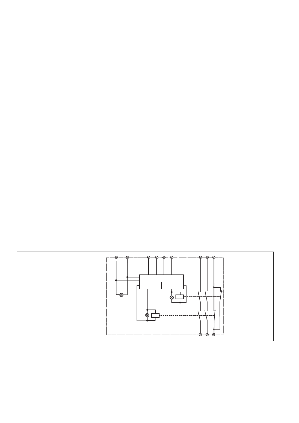
Fig. 1: Innenschaltbild /Connection
Diagram/ Schéma de principe
S11
S21
Y2
Y1
A2
A1
Steuerlogik/Control logic/
Logique de commande
K2
K1
Kanal/Channel/
Canal 1
Kanal/Channel/
Canal 2
13
23
31
32
24
14
"POWER"
"CH.1"
"CH.2"
The following is deemed improper use in
particular:
• Any component, technical oder electrical
modification to a product
• Use of a product outside the areas
described in the product documentation
• Any use that is not in accordance with the
documented technical details.
Est en particulier considéré comme non
conforme :
• toute modification structurelle, technique
ou électrique d'un produit
• I'utilisation d'un produit dans des
applications autres que celles décrites
dans la documentation des produits
• une utilisation autre que celle spécifiée
dans les caractéristiques techniques.
Nach Anlegen der Versorgungsspannung
U
B
und Schließen des Rückführkreises Y1-
Y2 ist das Gerät startbereit. Die LED
„POWER“ leuchtet.
• Werden die beiden Taster „gleichzeitig“,
d. h. innerhalb von 0,5 s betätigt, gehen
die beiden Ausgangsrelais K1 und K2 in
Arbeitsstellung und die Sicherheits-
kontakte 13-14/23-24 schließen, der
Hilfskontakt 31-32 öffnet. Die LED „CH.1“
und „CH.2“ leuchten.
When the operating voltage U
B
is supplied
and the feedback control loop is closed,
then the unit is ready for operation. The
LED "POWER" illminates.
• If buttons 1 and 2 are activated
'simultaneously' i.e. within 0.5 s, the
output relays K1 and K2 switch to
operating condition and the safety
contacts 13-14/23-24 close and the
auxiliary contact 31-32 opens. The LED
"CH.1" and "CH.2" illuminate.